Tiling Calibration
This example demonstrates how to calibrate the relationship between the camera sensor coordinate system and the microscope stage coordinate system. Calibration determines the physical pixel size (scale), axis mirroring, and the rotation angle between the camera sensor axes and the stage travel axes.
High-accuracy tiling acquisitions require stage coordinate shifts to map precisely to camera field-of-view (FOV) dimensions. The calibration procedure runs a multi-phase correlation algorithm that measures physical stage movements against image offsets:
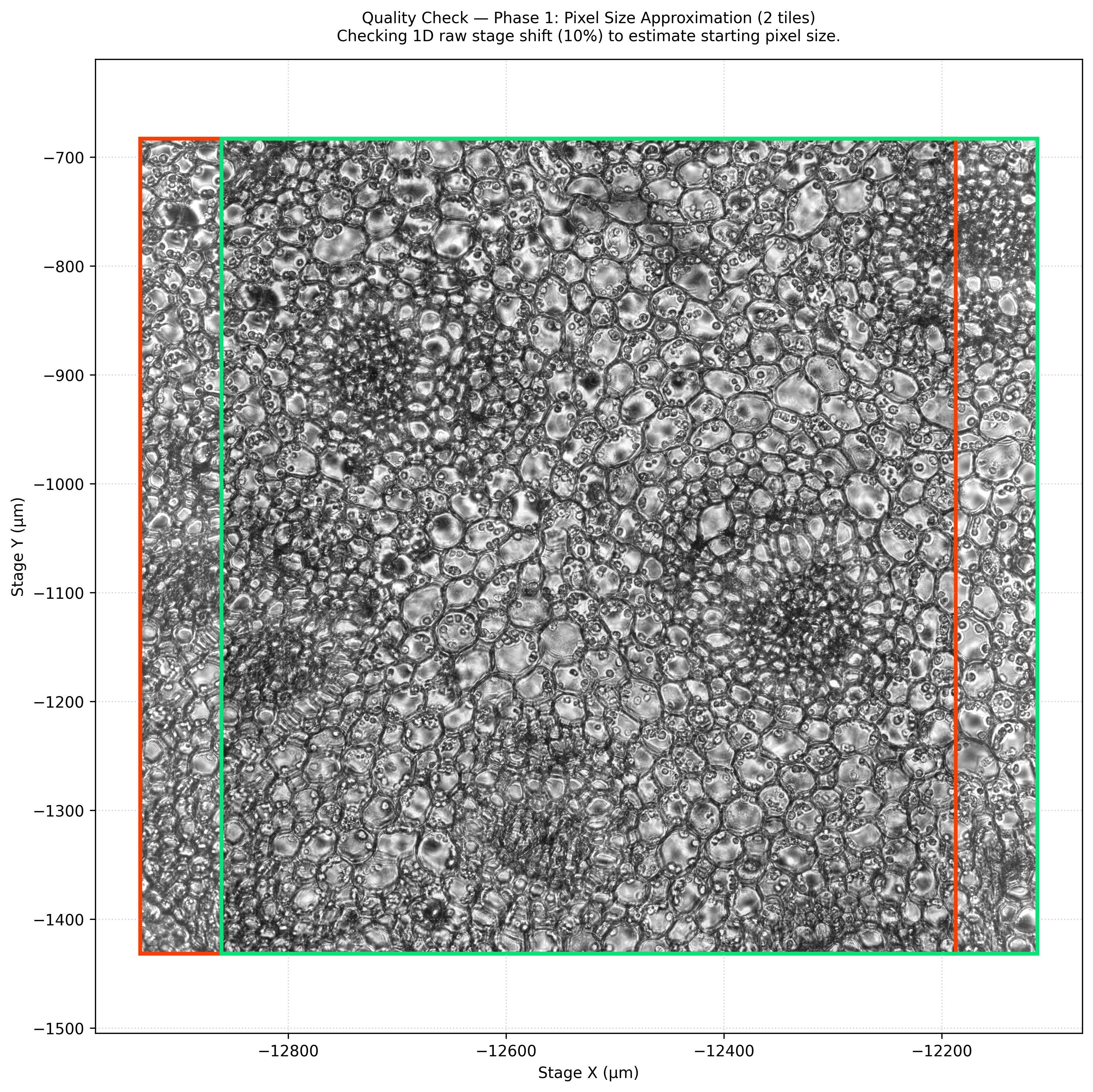
- Phase 1: Pixel Size Approximation: Drives a simple 1D stage displacement to estimate the spatial scale (µm/pixel).
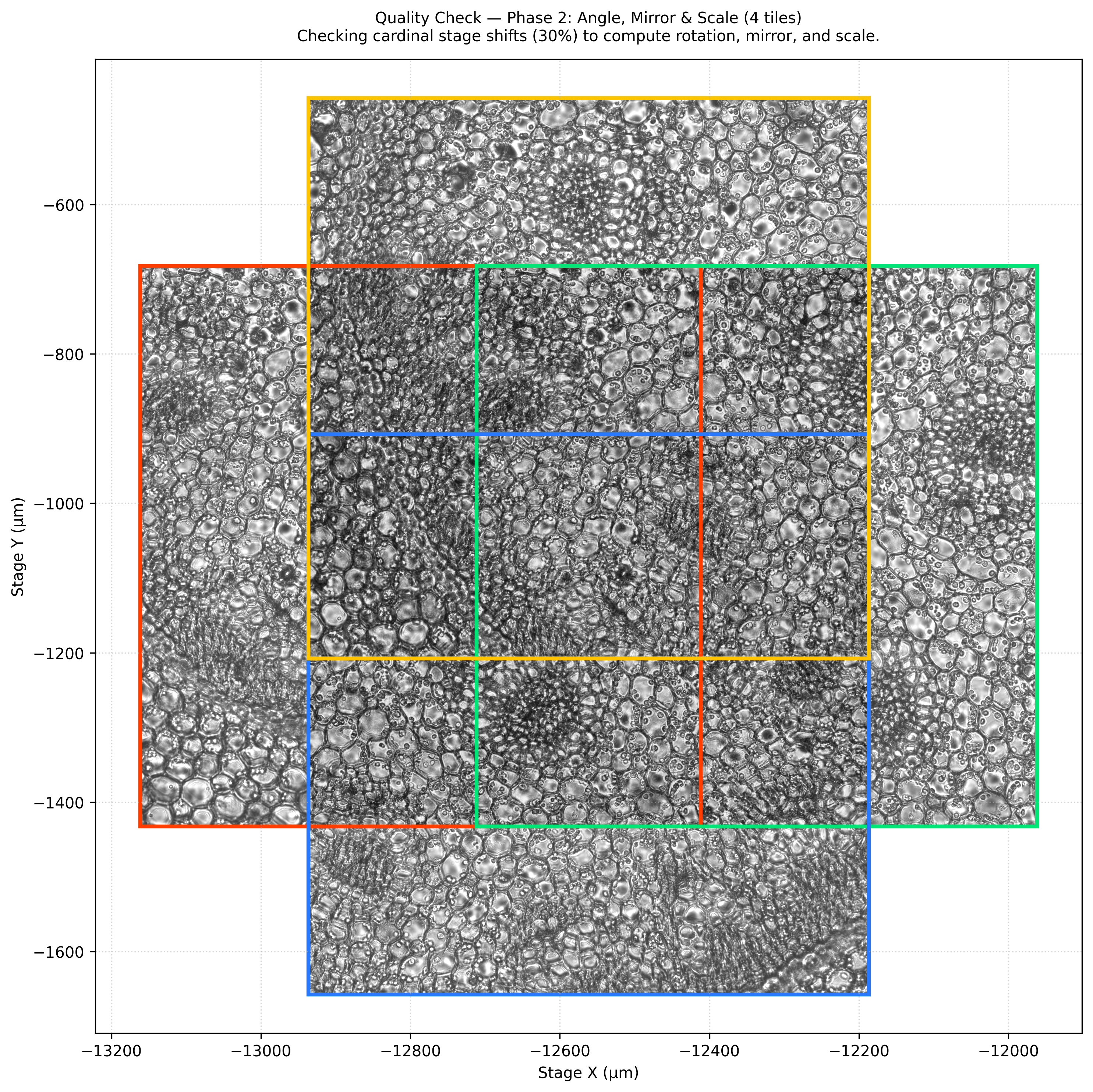
- Phase 2: Scale, Angle, and Mirroring Calibration: Acquires images in a four-cardinal-direction cross pattern to calculate rotation and detect axis mirroring.
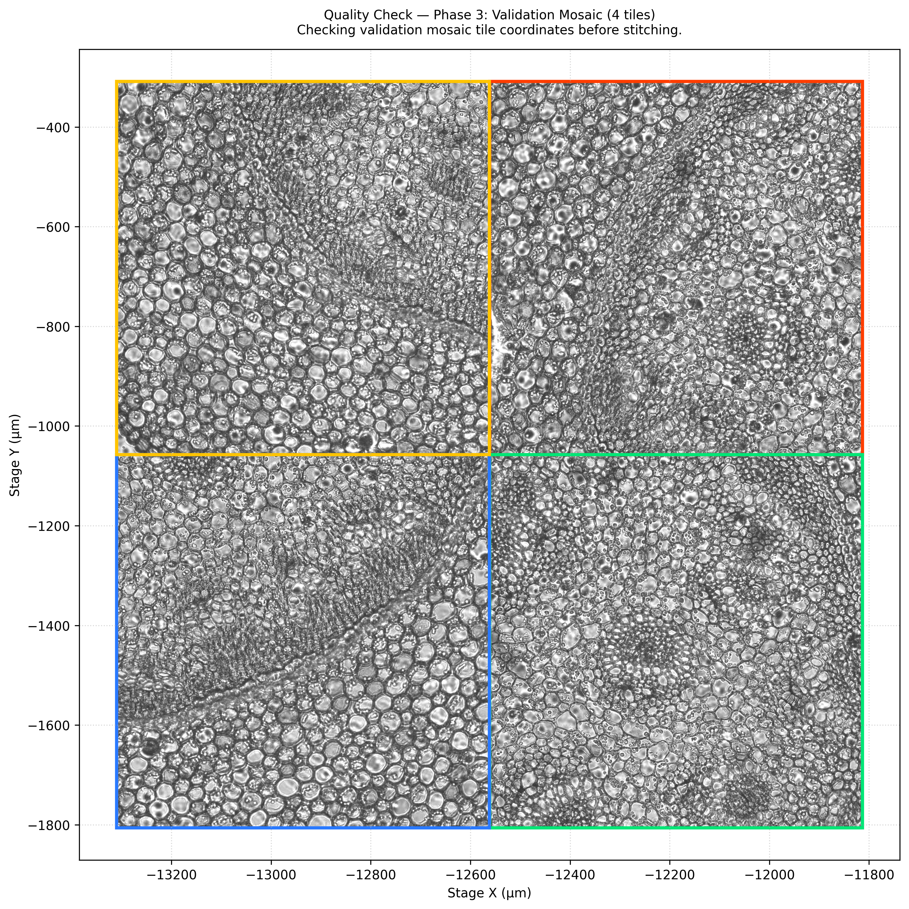
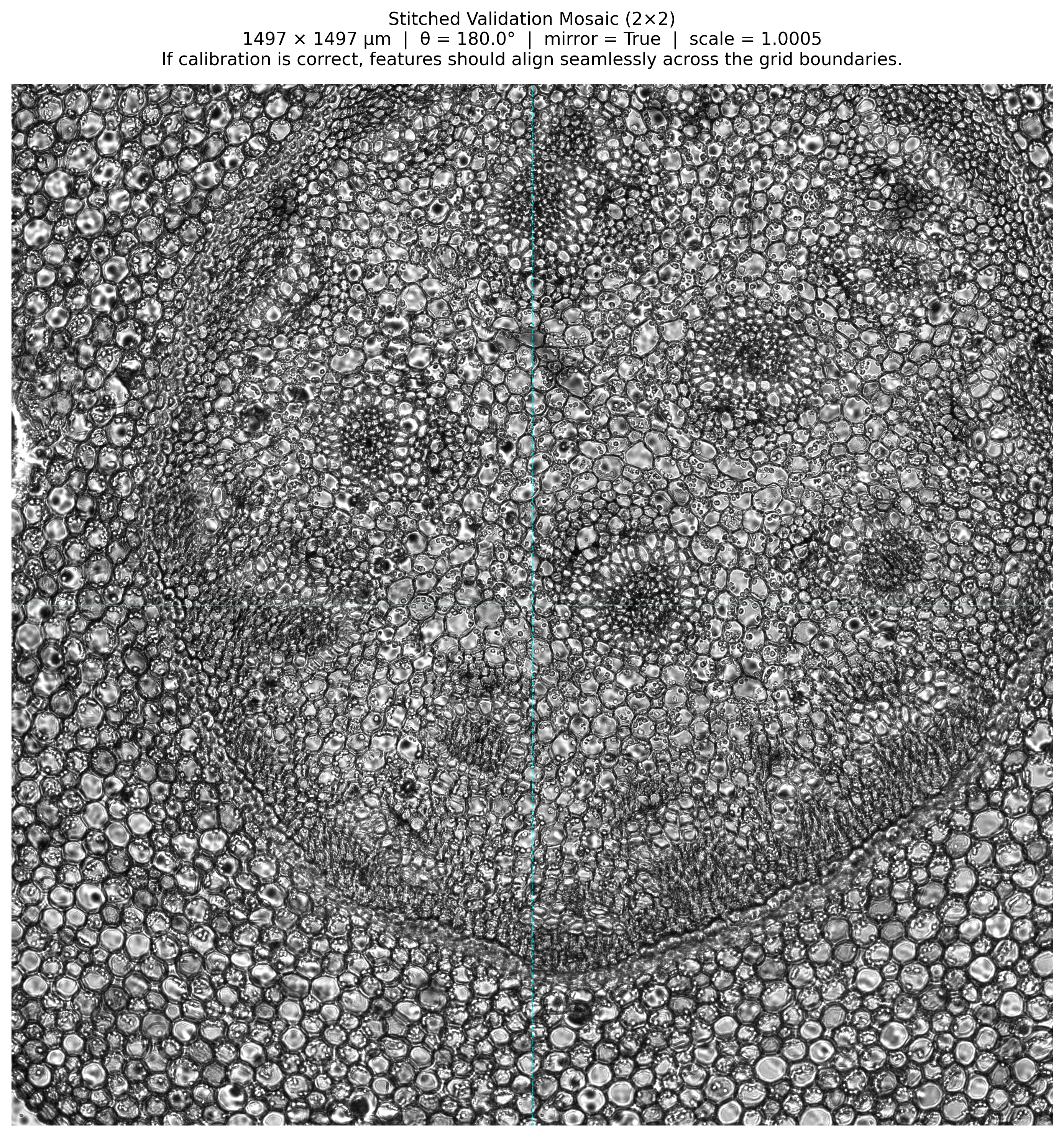
- Phase 3: Validation Mosaic: Runs a 2x2 tiling acquisition using the calibrated coordinates, proving alignment by stitching the tiles together.
Prerequisites
This example builds on the device exploration pattern introduced in Explore Devices and the channel definition concepts from Define Channels. The script uses the device map to locate the stage controllers (X_AXIS, Y_AXIS, MOVE_AXIS) and active optical components.
Before running the calibration, configure the following hardware-specific parameters in the script to match your setup:
- Camera Pixel Pitch (
CAMERA_PIXEL_PITCH_UM): The physical pixel size of the camera sensor in micrometers (e.g., 6.5 µm). Set this to match the camera pixel pitch configured in the Inscoper configurator during hardware setup. - Total Magnification (
OBJECTIVE_MAGNIFICATION): The total magnification factor of the optical path (e.g., 20.0). This represents the combined magnification of all magnifying devices in the optical path, including the objective lens, intermediate magnification changers, and auxiliary lenses. - Binning (
BINNING): The sensor pixel binning factor configured for the camera (e.g., 1).
The calibration script uses these parameters to calculate the expected theoretical pixel size. If the measured experimental pixel size deviates from this expected theoretical value by more than a set ratio (e.g., 5×), the calibration aborts to prevent alignment errors caused by incorrect hardware entries.
Overview
The workflow executes the following steps in order:
- Resolve the stage sub-devices: Identify the stage axis controller handles from the device map.
- Start the camera: Prepare the camera to stream images using the
SOFTWARE_TRIGGERmode. - Establish the reference channel: Load the Transmitted Light (TL) channel configuration parameters.
- Establish the reference position: Prompt the user to manually adjust the microscope stage to a target region containing visible, non-uniform features for correlation.
- Phase 1 (Pixel Size):
- Move the stage by a nominal offset in X (e.g., 10% of FOV).
- Correlate the reference and shifted images to calculate the raw pixel shift and approximate pixel size.
- Phase 2 (Angle, Mirror, Scale):
- Move the stage in a cross pattern: Left, Right, Top, and Bottom (e.g., 30% of FOV).
- Compute horizontal (Left ↔ Right) and vertical (Top ↔ Bottom) image translations using multi-scale Pearson correlation.
- Resolve the camera-to-stage rotation angle (\(\theta\)), identify axis mirroring, and determine the calibrated scale (µm/pixel).
- Phase 3 (Validation Mosaic):
- Acquire a 2x2 grid of overlapping tiles (e.g., 10% overlap) using the computed calibration parameters.
- Transform grid positions from camera-space coordinates to stage coordinates using the calibration matrix.
- Stitch the overlapping areas to confirm seamless visual tiling.
- Restore Stage: Return the stage to the original starting coordinates.
Calibration Outputs and Visualizations
The calibration workflow generates four diagnostic plots to visually inspect the alignment at each phase.
Phase 1: Pixel Size Approximation
Estimate the pixel size by shifting the stage along the X-axis and calculating the resulting translation in the camera sensor coordinate system.
Phase 2: Cardinal Shifts for Angle and Mirroring
Acquire four images displaced in a cross shape to calculate the precise rotation angle and detect sensor mirroring.
Phase 3-1: 2x2 Validation Layout
Plot the physical positions and bounds of the 2x2 validation tiles in stage space (microns).
Phase 3-2: Reconstructed Panorama
Stitch the validation tiles together using the computed calibration coefficients to verify seamless boundary matching.
Note
The examples on this page use a configuration named camera_and_microscope_and_fluo_source and a camera named MyCamera. Replace these values with the names defined in your own hardware configuration file.
Code Example
# ============================================================================
# CALIBRATION PARAMETERS
# ============================================================================

# Maximum acceptable ratio between experimental and theoretical pixel sizes.
# If the experimental pixel size is off by more than 5×, the system aborts
# as this indicates configuration issues (e.g., wrong objective selected).
PIXEL_SIZE_MAX_RATIO = 5.0

# ----------------------------------------------------------------------------
# Theoretical Pixel Size Calculation:
# ----------------------------------------------------------------------------
# The camera pixel pitch should match the value set during system configuration.
CAMERA_PIXEL_PITCH_UM = 6.5

# Total magnification factor of the optical path (objective magnification,
# intermediate magnification changers, and any auxiliary lenses).
OBJECTIVE_MAGNIFICATION = 20.0

BINNING = 1
pixel_size_um_theoric = CAMERA_PIXEL_PITCH_UM * BINNING / OBJECTIVE_MAGNIFICATION
pixel_size_nm_theoric = pixel_size_um_theoric * 1000.0

# We use the minimum dimension of the camera sensor as our base unit for shifts
# (e.g., shifts are expressed as 10% or 30% of the smaller camera dimension).
image_dim = min(camera_width, camera_height)


# ============================================================================
# IMAGE & CORRELATION UTILITIES
# ============================================================================


def compute_pearson_correlation(img1: np.ndarray, ox1: int, oy1: int,
                                img2: np.ndarray, ox2: int, oy2: int,
                                width: int, height: int) -> float:
    """Compute Pearson correlation coefficient between two image sub-regions."""
    if width <= 0 or height <= 0:
        return float('-inf')

    # Flatten the 2D regions of interest into 1D vectors
    patch1 = img1[oy1:oy1 + height, ox1:ox1 + width].ravel()
    patch2 = img2[oy2:oy2 + height, ox2:ox2 + width].ravel()

    if len(patch1) == 0:
        return float('-inf')

    # If either patch is completely uniform (all pixels have the same value),
    # its variance is 0, which makes the correlation mathematically undefined.
    # We return 0.0 to prevent warnings/errors and continue searching.
    if np.all(patch1 == patch1[0]) or np.all(patch2 == patch2[0]):
        return 0.0

    # Compute correlation coefficient matrix using NumPy and extract the cross-correlation element
    return float(np.corrcoef(patch1, patch2)[0, 1])


def _search_offset(img1: np.ndarray, img2: np.ndarray,
                   x_center: int, y_center: int,
                   x_radius: int, y_radius: int) -> Tuple[int, int, float]:
    """Brute-force search for the (x, y) offset that maximizes Pearson correlation within [center ± radius]."""
    h1, w1 = img1.shape
    h2, w2 = img2.shape
    best_x, best_y = 0, 0
    best_corr = float('-inf')

    # Loop over the rectangular search window [center ± radius]
    for y_off in range(y_center - y_radius, y_center + y_radius + 1):
        for x_off in range(x_center - x_radius, x_center + x_radius + 1):

            # Determine the width and height of the overlapping region
            corr_width = w1 - abs(x_off)
            corr_height = h1 - abs(y_off)

            if corr_width <= 0 or corr_height <= 0:
                continue

            # Determine where to crop each image.
            # If x_off is positive, img2 is shifted right relative to img1.
            # If negative, img2 is shifted left.
            ox1 = max(0, x_off)
            oy1 = max(0, y_off)
            ox2 = max(0, -x_off)
            oy2 = max(0, -y_off)

            # Clamp overlapping box to ensure it does not exceed the boundaries of either image
            corr_width = min(corr_width, w1 - ox1, w2 - ox2)
            corr_height = min(corr_height, h1 - oy1, h2 - oy2)

            if corr_width <= 0 or corr_height <= 0:
                continue

            # Compute correlation for this translation hypothesis
            corr = compute_pearson_correlation(img1, ox1, oy1,
                                               img2, ox2, oy2,
                                               corr_width, corr_height)

            # Keep track of the translation that yields the highest correlation coefficient
            if corr > best_corr:
                best_x = x_off
                best_y = y_off
                best_corr = corr

    return best_x, best_y, best_corr


def get_offset_by_correlation(img1: np.ndarray, img2: np.ndarray) -> Tuple[int, int, float]:
    """Multi-scale recursive correlation search (coarse-to-fine) to find the pixel translation offset between two images."""
    DIM_THRESHOLD = 256
    RATIO = 4

    h1, w1 = img1.shape

    if w1 * h1 > DIM_THRESHOLD * DIM_THRESHOLD:
        # Coarse stage: downsample images by 4× and find the coarse offset recursively.
        mini1 = block_reduce(img1, (RATIO, RATIO), np.mean)
        mini2 = block_reduce(img2, (RATIO, RATIO), np.mean)

        ox_mini, oy_mini, _ = get_offset_by_correlation(mini1, mini2)

        # Fine stage: scale the coarse offset back to full resolution,
        # then scan a small area of ±4 pixels to find the precise sub-pixel seam
        return _search_offset(img1, img2,
                              ox_mini * RATIO, oy_mini * RATIO,
                              RATIO, RATIO)
    else:
        # Small images: do a brute-force sweep up to 80% of the image size
        max_ratio = 0.8
        x_max = int(w1 * max_ratio)
        y_max = int(w1 * max_ratio)
        return _search_offset(img1, img2, 0, 0, x_max, y_max)


def acquire_images(positions: List[Tuple[float, float]]) -> List[np.ndarray]:
    """Acquire camera images at the given stage positions (nm) and return them as a list of 2D numpy arrays."""
    # Clear previous images from the listener buffer
    my_listener._received_images.clear()

    tiling_status = []
    for x_pos, y_pos in positions:
        tile_status = inscoper_api.Status()

        # Load Transmitted Light channel parameters (objective turret, shutters, power, etc.)
        for sub_device_id, value in tl_channel_description.items():
            if sub_device_id is not None:
                tile_status.addParam(sub_device_id, value)

        # Clamp target coordinates to nearest multiple of the physical step size constraints
        target_x = int(round(x_pos / x_step)) * int(x_step)
        target_y = int(round(y_pos / y_step)) * int(y_step)
        tile_status.addParam(x_axis_sub_device_id, target_x)
        tile_status.addParam(y_axis_sub_device_id, target_y)

        # Add camera trigger tags
        tile_status.addTag("MyCamera")
        tile_status.addTag("SOFTWARE_TRIGGER")

        tiling_status.append(tile_status)

    # Load the sequence of target statuses and run it asynchronously
    my_bridge.loadSequence(2, "Acquisition", tiling_status)
    my_bridge.runSequence(2, False)

    # Retrieve images collected by the listener
    received_images = my_listener.getReceivedImages()

    numpy_images = []
    if received_images:
        # Determine bit-depth and dimension parameters from the first frame
        first_image = received_images[0]
        W = first_image.getWidth()
        H = first_image.getHeight()
        pixel_size_bytes = first_image.getPixelSize()
        bit_depth = first_image.getBitDepth()
        bytes_per_value = bit_depth // 8
        values_per_pixel = pixel_size_bytes // bytes_per_value

        # Convert each image from raw byte arrays to 2D float64 numpy matrices
        for image in received_images:
            image_data = image.getImageData()
            img = np.reshape(image_data, (H, W, values_per_pixel))
            img_channel = img[:, :, 0].astype(np.float64)
            numpy_images.append(img_channel)

    return numpy_images


def plot_and_save_stage(numpy_images: List[np.ndarray], positions: List[Tuple[float, float]], stage_name: str, subtitle: str, pixel_size_um: float):
    """Plot acquired tiles in stage-space coordinates (µm) and save as a transparent PNG."""
    fig, ax = plt.subplots(figsize=(10, 10))
    ax.set_xlabel("Stage X (µm)")
    ax.set_ylabel("Stage Y (µm)")

    # Color palette for drawing distinct borders around each tile
    edge_colors = ['#FF3D00', '#00E676', '#2979FF', '#FFC400', '#E040FB', '#00E5FF', '#FF6D00', '#76FF03']
    all_lefts, all_rights, all_bottoms, all_tops = [], [], [], []

    # Map each tile image into physical stage-space coordinates
    for idx, img in enumerate(numpy_images):
        x_pos, y_pos = positions[idx]
        cx = x_pos / 1000.0  # Convert nanometers to micrometers
        cy = y_pos / 1000.0

        # Calculate half width/height in micrometers
        half_w = (img.shape[1] * pixel_size_um) / 2.0
        half_h = (img.shape[0] * pixel_size_um) / 2.0

        # Calculate bounding coordinates
        left = cx - half_w
        right = cx + half_w
        bottom = cy - half_h
        top = cy + half_h

        all_lefts.append(left)
        all_rights.append(right)
        all_bottoms.append(bottom)
        all_tops.append(top)

        # Plot the tile overlaying its physical location
        extent = [left, right, bottom, top]
        ax.imshow(img, cmap='gray', extent=extent, alpha=0.8, origin='upper')

        # Draw a solid border to visually distinguish overlapping sections
        color = edge_colors[idx % len(edge_colors)]
        rect = plt.Rectangle((left, bottom), 2 * half_w, 2 * half_h,
                             fill=False, edgecolor=color, linewidth=2.5, linestyle='-')
        ax.add_patch(rect)

    # Set coordinate limits using all tiles with a 5% margin to prevent cropping
    if all_lefts:
        min_x = min(all_lefts)
        max_x = max(all_rights)
        min_y = min(all_bottoms)
        max_y = max(all_tops)
        pad_x = (max_x - min_x) * 0.05 if max_x != min_x else 10.0
        pad_y = (max_y - min_y) * 0.05 if max_y != min_y else 10.0
        ax.set_xlim(min_x - pad_x, max_x + pad_x)
        ax.set_ylim(min_y - pad_y, max_y + pad_y)

    ax.set_aspect('equal', 'datalim')

    title_text = f"Quality Check — {stage_name} ({len(numpy_images)} tiles)"
    if subtitle:
        title_text += f"\n{subtitle}"
    ax.set_title(title_text, fontsize=10, pad=12)
    plt.grid(True, linestyle=':', alpha=0.5)
    plt.tight_layout()

    # Save the visualization plot as a transparent PNG in the script folder
    script_dir = os.path.dirname(os.path.abspath(__file__))
    filename = stage_name.lower().replace(":", "").replace(" ", "_").replace(",", "").replace("&", "") + ".png"
    save_path = os.path.join(script_dir, filename)
    fig.savefig(save_path, dpi=300, transparent=True, bbox_inches='tight')
    print(f"    [Saved Plot] {save_path}")
    plt.show()


def mosaic_convert(x: float, y: float, theta: float, mirror: bool) -> Tuple[float, float]:
    """Convert camera-space offsets to stage-space offsets by applying mirror swap and 2D rotation."""
    if mirror:
        x, y = y, x

    x_res = x * math.cos(theta) - y * math.sin(theta)
    y_res = x * math.sin(theta) + y * math.cos(theta)
    return x_res, y_res


# ──────────────────────────────────────────────────────────────
# Step 4: Wait for the user to adjust the X and Y position on the microscope
# ──────────────────────────────────────────────────────────────
input(
    "\n[Step 4] Position the stage over a FEATURE-RICH area\n"
    "         (e.g., tissue, cells, text on a slide).\n"
    "         Avoid blank or uniform areas — correlation needs texture.\n"
    "         Press Enter when ready... "
)

# ──────────────────────────────────────────────────────────────
# Step 5: Get current stage positions and define the tiling grid
# ──────────────────────────────────────────────────────────────
current_x = my_bridge.getLongValue(x_axis_sub_device_id)
current_y = my_bridge.getLongValue(y_axis_sub_device_id)
print(f"Current X position: {current_x} nm")
print(f"Current Y position: {current_y} nm")

# ==============================================================
# PHASE 1: Pixel Size Approximation (2 images)
# ==============================================================
print("\n" + "=" * 70)
print("  PHASE 1: Pixel size approximation")
print("=" * 70)

# Shift the stage by 10% of the image size in the X direction (in nanometers).
# This is a one-dimensional translation used to calculate the starting scale ratio.
shift_10pct_nm = 0.1 * image_dim * pixel_size_nm_theoric

positions_p1 = [
    (current_x, current_y),                        # Center frame
    (current_x + shift_10pct_nm, current_y),       # Offset frame (10% shift in X)
]

print(f"    Shift: {shift_10pct_nm:.0f} nm ({shift_10pct_nm / 1000:.1f} µm)")
print("    Acquiring 2 images...")

# Run sequence and collect images
images_p1 = acquire_images(positions_p1)
if len(images_p1) < 2:
    raise RuntimeError("Phase 1 failed: did not receive 2 images")

# Display the two tiles in physical coordinates for user verification
plot_and_save_stage(
    images_p1, positions_p1,
    stage_name="Phase 1: Pixel Size Approximation",
    subtitle="Checking 1D raw stage shift (10%) to estimate starting pixel size.",
    pixel_size_um=pixel_size_um_theoric
)

img_center = images_p1[0]
img_right10 = images_p1[1]

# Correlate center frame with shifted frame to calculate the pixel displacement
print("    Computing correlation (center ↔ right+10%)...")
t0 = time.time()
offset_x, offset_y, corr = get_offset_by_correlation(img_center, img_right10)
dt = time.time() - t0
offset_mag = math.sqrt(offset_x ** 2 + offset_y ** 2)

print(f"    Offset: ({offset_x}, {offset_y}) px  |  magnitude: {offset_mag:.1f} px")
print(f"    Correlation: {corr:.4f}  |  Time: {dt:.2f}s")

# Check for failure to translate: if magnitude is zero, correlation or movement failed
if offset_mag == 0:
    raise RuntimeError(
        "Phase 1 failed: zero offset. "
        "Ensure the sample has visible features and the stage actually moved."
    )

# Compute the first approximation of the experimental pixel size:
# Experimental pixel size = stage displacement (in nm) / pixel displacement (magnitude in pixels)
pixel_size_nm_exp10 = (image_dim * 0.1 * pixel_size_nm_theoric) / offset_mag
ratio_10 = pixel_size_nm_exp10 / pixel_size_nm_theoric
print(f"    Experimental pixel size: {pixel_size_nm_exp10:.2f} nm ({pixel_size_nm_exp10 / 1000:.4f} µm)")
print(f"    Ratio (exp / theoric): {ratio_10:.3f}")

# Abort if the pixel size ratio is highly abnormal (greater than 5× or less than 0.2×).
if ratio_10 > PIXEL_SIZE_MAX_RATIO or ratio_10 < 1.0 / PIXEL_SIZE_MAX_RATIO:
    raise RuntimeError(
        f"Phase 1 failed: pixel size ratio {ratio_10:.3f} exceeds threshold (±{PIXEL_SIZE_MAX_RATIO}×).\n"
        f"  Theoric:      {pixel_size_nm_theoric:.1f} nm\n"
        f"  Experimental: {pixel_size_nm_exp10:.1f} nm\n"
        f"  Check CAMERA_PIXEL_PITCH_UM ({CAMERA_PIXEL_PITCH_UM}) and OBJECTIVE_MAGNIFICATION ({OBJECTIVE_MAGNIFICATION})."
    )

# ==============================================================
# PHASE 2: Angle, Mirror and Scale (4 images)
# ==============================================================
print("\n" + "=" * 70)
print("  PHASE 2: Angle, mirror and scale computation")
print("=" * 70)

# Move the stage by 30% of the image size to each cardinal direction (Left, Right, Top, Bottom).
# This distance provides substantial overlap while introducing clear cross-axis shifts.
offset_ratio = 0.3
cardinal_offset_nm = image_dim * offset_ratio * pixel_size_nm_exp10

positions_p2 = [
    (current_x - cardinal_offset_nm, current_y),     # Left position
    (current_x + cardinal_offset_nm, current_y),     # Right position
    (current_x, current_y - cardinal_offset_nm),     # Top position
    (current_x, current_y + cardinal_offset_nm),     # Bottom position
]

print(f"    Cardinal offset: {cardinal_offset_nm:.0f} nm ({cardinal_offset_nm / 1000:.1f} µm)")
print("    Acquiring 4 images (left, right, top, bottom)...")

# Run sequence to collect the 4 cardinal tiles
images_p2 = acquire_images(positions_p2)
if len(images_p2) < 4:
    raise RuntimeError("Phase 2 failed: did not receive 4 images")

# Display overlapping cardinal tiles in stage-space for visual check
plot_and_save_stage(
    images_p2, positions_p2,
    stage_name="Phase 2: Angle, Mirror and Scale",
    subtitle="Checking cardinal stage shifts (30%) to compute rotation, mirror, and scale.",
    pixel_size_um=pixel_size_nm_exp10 / 1000.0
)

img_left = images_p2[0]
img_right = images_p2[1]
img_top = images_p2[2]
img_bottom = images_p2[3]

# Correlate Left frame with Right frame to evaluate horizontal translation parameters
print("    Computing horizontal correlation (left ↔ right)...")
t0 = time.time()
h_off_x, h_off_y, h_corr = get_offset_by_correlation(img_left, img_right)
dt = time.time() - t0
print(f"    H offset: ({h_off_x}, {h_off_y}) px  |  corr: {h_corr:.4f}  |  {dt:.2f}s")

# Correlate Top frame with Bottom frame to evaluate vertical translation parameters
print("    Computing vertical correlation (top ↔ bottom)...")
t0 = time.time()
v_off_x, v_off_y, v_corr = get_offset_by_correlation(img_top, img_bottom)
dt = time.time() - t0
print(f"    V offset: ({v_off_x}, {v_off_y}) px  |  corr: {v_corr:.4f}  |  {dt:.2f}s")

# ── Compute rotation angles in radians ──
horizontal_angle = (math.atan2(h_off_y, h_off_x) + 2 * math.pi) % (2 * math.pi)
vertical_angle = (math.atan2(v_off_y, v_off_x) + 2 * math.pi) % (2 * math.pi)

print(f"\n    Raw angles:")
print(f"      Horizontal: {math.degrees(horizontal_angle):.2f}°  ({horizontal_angle:.6f} rad)")
print(f"      Vertical:   {math.degrees(vertical_angle):.2f}°  ({vertical_angle:.6f} rad)")

# Ensure horizontal and vertical angles are within π of each other for normalization
while abs(horizontal_angle - vertical_angle) > math.pi:
    if horizontal_angle < vertical_angle:
        horizontal_angle += 2 * math.pi
    else:
        vertical_angle += 2 * math.pi

# ── Determine if camera sensor axes are mirrored relative to stage axes ──
# Under nominal rotation, the vertical angle should lead or follow the horizontal one.
# An inverse relationship indicates axis mirroring.
mirror = vertical_angle < horizontal_angle

# ── Adjust angles based on mirror state (matching Java IIS algorithm) ──
if mirror:
    horizontal_angle -= math.pi / 2
else:
    vertical_angle -= math.pi / 2
    vertical_angle = -vertical_angle
    horizontal_angle = -horizontal_angle

print(f"\n    Adjusted angles:")
print(f"      Horizontal: {math.degrees(horizontal_angle):.2f}°  ({horizontal_angle:.6f} rad)")
print(f"      Vertical:   {math.degrees(vertical_angle):.2f}°  ({vertical_angle:.6f} rad)")
print(f"      Mirror:     {mirror}")

# ── Compute refined pixel sizes ──
h_magnitude = math.sqrt(h_off_x ** 2 + h_off_y ** 2)
v_magnitude = math.sqrt(v_off_x ** 2 + v_off_y ** 2)

if h_magnitude == 0 or v_magnitude == 0:
    raise RuntimeError(
        "Phase 2 failed: zero offset in cardinal correlation. "
        "The stage may not be moving, or the sample lacks features."
    )

# Since we moved 30% left and 30% right, the total distance between left/right is 60% (2 * offset_ratio).
# Refined pixel size = total stage shift distance (in nm) / measured pixel translation magnitude
pixel_size_nm_hori = (image_dim * 2 * offset_ratio * pixel_size_nm_exp10) / h_magnitude
pixel_size_nm_verti = (image_dim * 2 * offset_ratio * pixel_size_nm_exp10) / v_magnitude
pixel_size_nm_exp = (pixel_size_nm_hori + pixel_size_nm_verti) / 2.0

print(f"\n    Refined pixel sizes:")
print(f"      Horizontal: {pixel_size_nm_hori:.2f} nm")
print(f"      Vertical:   {pixel_size_nm_verti:.2f} nm")
print(f"      Average:    {pixel_size_nm_exp:.2f} nm")

# ── Final calibration parameters ──
# theta: Average of horizontal and vertical angles
# scale: Ratio of theoretical pixel size to experimental pixel size
theta = (horizontal_angle + vertical_angle) / 2.0
scale = pixel_size_nm_theoric / pixel_size_nm_exp

# ==============================================================
# OUTPUT RESULTS
# ==============================================================
print("\n" + "=" * 70)
print("  CALIBRATION RESULTS")
print("=" * 70)

calibration = {
    "StageCalibAngle": theta,
    "StageCalibMirror": mirror,
    "StageCalibStaticScale": scale,
}

print(f"\n    Result: {calibration}\n")
print(f"    Angle (rad):     {theta:.6f} ({math.degrees(theta):.2f}°)")
print(f"    Mirror:          {mirror}")
print(f"    Scale:           {scale:.6f}")
print(f"    Theoric pixel:   {pixel_size_nm_theoric:.2f} nm")
print(f"    Exp. pixel:      {pixel_size_nm_exp:.2f} nm")

# ==============================================================
# PHASE 3: Validation Mosaic (2×2, 0% overlap)
# ==============================================================
print("\n" + "=" * 70)
print("  PHASE 3: Validation mosaic (2×2)")
print("=" * 70)

# Field-of-view in nanometers using the refined experimental pixel size
fov_x_nm = camera_width * pixel_size_nm_exp
fov_y_nm = camera_height * pixel_size_nm_exp

mosaic_positions = []
mosaic_grid_coords = []

# Generate coordinate offsets for a 2x2 grid centered on the original position.
# Col/Row coordinates are offset by ±0.5 FOV from center.
for j in range(2):
    # Snake pattern: reverse column order on odd rows to minimize travel
    cols = range(2 - 1, -1, -1) if j % 2 != 0 else range(2)
    for i in cols:
        # Camera-space offset from center (in nanometers)
        cam_x = (i - 0.5) * fov_x_nm
        cam_y = (j - 0.5) * fov_y_nm

        # Apply computed calibration (mirror, rotation, scale) to convert
        # camera coordinate offsets to stage motor offsets.
        stage_dx, stage_dy = mosaic_convert(cam_x, cam_y, theta, mirror)
        stage_dx *= scale
        stage_dy *= scale

        target_x = current_x + stage_dx
        target_y = current_y + stage_dy

        mosaic_positions.append((target_x, target_y))
        mosaic_grid_coords.append((j, i))

print(f"    FOV: {fov_x_nm / 1000:.1f} × {fov_y_nm / 1000:.1f} µm")
print(f"    Acquiring {len(mosaic_positions)} tiles...")

# Run the sequence to acquire the 2x2 validation tiles
mosaic_images = acquire_images(mosaic_positions)

if len(mosaic_images) >= 4:
    # Plot individual tile bounds in stage-space for checking overlaps
    plot_and_save_stage(
        mosaic_images, mosaic_positions,
        stage_name="Phase 3: Validation Mosaic",
        subtitle="Checking validation mosaic tile coordinates before stitching.",
        pixel_size_um=pixel_size_nm_exp / 1000.0
    )

    # Stitch the 2x2 mosaic tiles using simple pixel boundary alignment (no blending)
    H, W = mosaic_images[0].shape
    pano_width = 2 * W
    pano_height = 2 * H

    pano = np.zeros((pano_height, pano_width), dtype=np.float32)
    weights = np.zeros((pano_height, pano_width), dtype=np.float32)

    # Accumulate pixels into the panorama grid
    for idx, img in enumerate(mosaic_images):
        if idx >= len(mosaic_grid_coords):
            break
        j, i = mosaic_grid_coords[idx]
        start_x = i * W
        start_y = j * H
        end_x = start_x + W
        end_y = start_y + H

        pano[start_y:end_y, start_x:end_x] += img
        weights[start_y:end_y, start_x:end_x] += 1.0

    # Normalize overlapping boundaries
    mask = weights > 0
    pano[mask] /= weights[mask]

    # Display and save the final stitched mosaic panorama
    total_fov_x_um = pano_width * pixel_size_nm_exp / 1000
    total_fov_y_um = pano_height * pixel_size_nm_exp / 1000

    fig, ax = plt.subplots(figsize=(10, 10))
    ax.imshow(pano, cmap="gray")
    title_text = (
        f"Stitched Validation Mosaic (2×2)\n"
        f"{total_fov_x_um:.0f} × {total_fov_y_um:.0f} µm  |  "
        f"θ = {math.degrees(theta):.1f}°  |  "
        f"mirror = {mirror}  |  "
        f"scale = {scale:.4f}\n"
        "If calibration is correct, features should align seamlessly across the grid boundaries."
    )
    ax.set_title(title_text, fontsize=11, pad=12)

    # Draw a dotted validation grid overlay in cyan to visually highlight seams
    ax.axhline(y=H, color="cyan", linewidth=0.8, alpha=0.5, linestyle="--")
    ax.axvline(x=W, color="cyan", linewidth=0.8, alpha=0.5, linestyle="--")

    ax.axis("off")
    plt.tight_layout()

    # Save the validation mosaic image to the script folder
    script_dir = os.path.dirname(os.path.abspath(__file__))
    save_path = os.path.join(script_dir, "stitched_validation_mosaic.png")
    fig.savefig(save_path, dpi=300, transparent=True, bbox_inches='tight')
    print(f"    [Saved Plot] {save_path}")

    print("\n    Displaying validation mosaic...")
    print("    → If tiles align well (no visible seams), calibration is good!")
    print("    → If tiles overlap or have gaps, check the configuration.")
    plt.show()
else:
    print("    WARNING: Insufficient images for validation mosaic.")

# ──────────────────────────────────────────────────────────────
# Move stage back to center position (original starting coordinates)
# ──────────────────────────────────────────────────────────────
print("\n[Cleanup] Returning stage to center position...")

return_status = inscoper_api.Status()
for sub_device_id, value in tl_channel_description.items():
    if sub_device_id is not None:
        return_status.addParam(sub_device_id, value)
return_status.addParam(x_axis_sub_device_id, int(current_x))
return_status.addParam(y_axis_sub_device_id, int(current_y))
return_status.addTag("MyCamera")
return_status.addTag("SOFTWARE_TRIGGER")

my_bridge.loadSequence(2, "Acquisition", [return_status])
my_bridge.runSequence(2, False)

# ──────────────────────────────────────────────────────────────
# Final summary output
# ──────────────────────────────────────────────────────────────
print("\n" + "=" * 70)
print("  CALIBRATION COMPLETE")
print("=" * 70)
print(f"\n    Result: {calibration}\n")
print("    To apply this calibration when generating tiling positions:")
print()
print("      # Camera offset → stage offset")
print("      if mirror:")
print("          cam_x, cam_y = cam_y, cam_x")
print("      stage_x = scale * (cam_x * cos(θ) - cam_y * sin(θ))")
print("      stage_y = scale * (cam_x * sin(θ) + cam_y * cos(θ))")
print()