TIRF
The TIRF add-on controls Total Internal Reflection Fluorescence (TIRF) illumination through the Inscoper Maxillda laser scanning device.
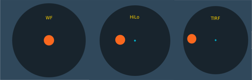
The add-on positions the excitation laser in the back focal plane of the objective. The distance between the laser spot and the optical axis sets the incidence angle at the coverslip, and therefore the illumination regime:
- Epifluorescence (widefield): the laser is centered on the optical axis; the beam crosses the full sample depth.
- HILO (Highly Inclined and Laminated Optical sheet): the laser is off-axis, below the critical angle; the beam exits the coverslip as an inclined sheet.
- TIRF: the laser reaches the critical angle; the beam is totally reflected and only the evanescent field excites the sample.
The workflow has three stages: calibrate the TIRF position, create a TIRF channel, and select this channel in an acquisition sequence.
Optical Calibration
The calibration defines the circle, in the back focal plane, on which the laser reaches the critical angle. All TIRF channels use this circle as their reference.
A calibration is stored for each combination of the devices declared as calibration discriminants in the system configuration (for example, the excitation laser line or the objective). The software loads the calibration that matches the current device state when you open the calibration view. Because the critical angle depends on the excitation wavelength, calibrate each laser line used for TIRF imaging.
Tip
Perform the calibration on a sample that has a strong, uniform fluorescent signal at the coverslip surface and an aqueous medium above it, such as fluorescent beads adsorbed onto a glass-bottom dish. The loss of out-of-focus background is then easy to observe.
Calibration Procedure
Before you start, load a TIRF channel.
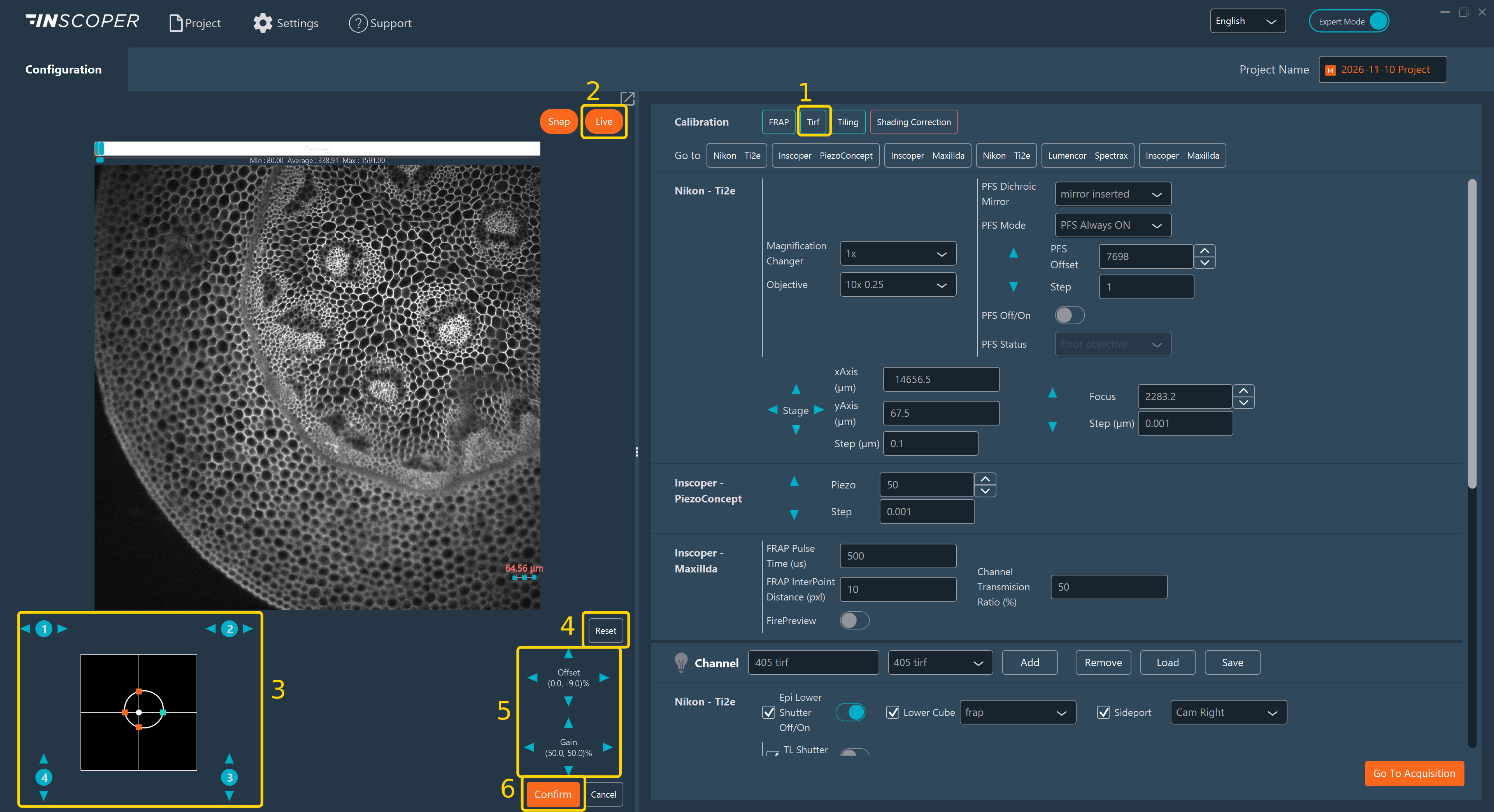
- In the Calibration section, click Tirf.
- Click Live to display the camera feed.
- Use the calibration pad to place the four reference points on the TIRF circle. Each point has its own control, marked with a blue number:
- Controls 1 and 2 move the left and right points along the horizontal axis.
- Controls 3 and 4 move the top and bottom points along the vertical axis.
- Clicking an arrow selects the corresponding point and sends the laser to that position. Move each point outward, away from the center, until the image switches to TIRF illumination: the out-of-focus background disappears and only the structures in contact with the coverslip remain visible. Stop at the first position where this transition occurs. Repeat for the four points.
- If required, click Reset to return the four points to their default positions and restart the calibration. Confirm the reset in the dialog box.
- In Expert Mode only, use the Offset and Gain controls to adjust the global alignment of the laser scanning device. Offset shifts the center of the circle along X and Y; Gain scales the circle along X and Y. Both values are displayed as percentages.
- Click Confirm to save the calibration. Click Cancel to close the view without saving.
Note
The Offset and Gain values describe the alignment of the Maxillda device itself. They are shared by every TIRF calibration, regardless of the laser line. Modifying them affects all stored calibrations. In Expert Mode, Reset also restores the default Offset (0, 0) and Gain (50, 50) values. These values are set once during installation. Adjust them only if the optical module is removed from the system and then reinstalled.
TIRF Channel Configuration
TIRF imaging requires a dedicated channel. Configure it in the device panel of the Configuration tab.
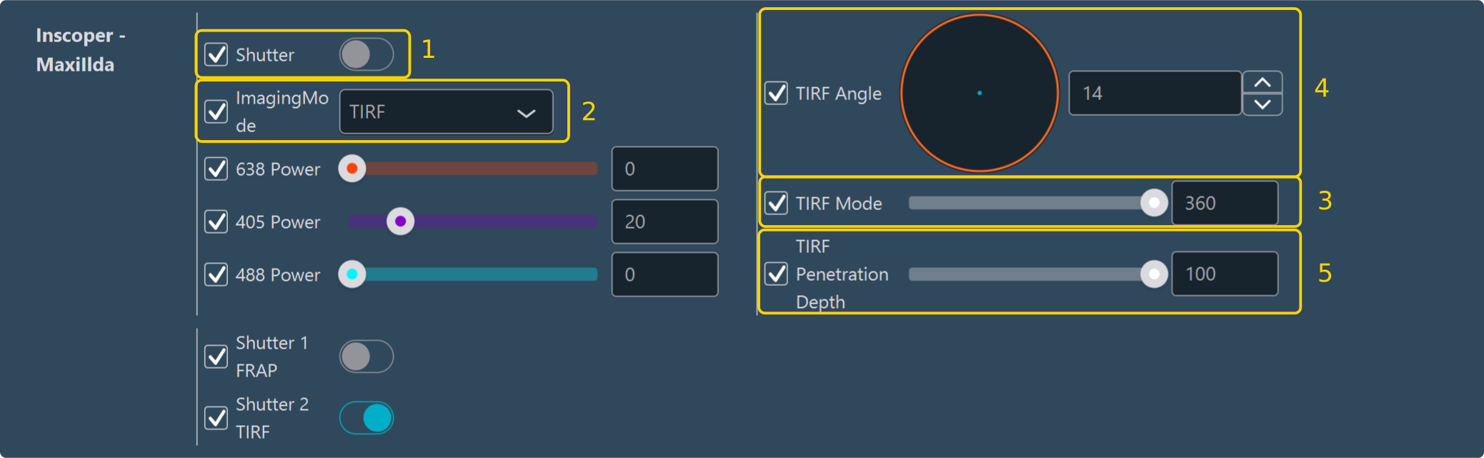
- Disable the Maxillda Shutter for a TIRF channel (On is for the FRAP channel).
- Set ImagingMode to TIRF.
-
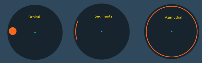
Set TIRF Mode, the angular extent of the illumination pattern around the optical axis, in degrees:
- 360: the laser sweeps the full circle (azimuthal, or ring, TIRF). This averages the illumination over all directions and reduces interference fringes and shadowing artifacts.
- Lower values: Segmental TIRF, the laser sweeps an arc of the specified length. This begins to average out interference fringes and is useful if physical obstructions in the optical path prevent a full 360° sweep. The TIRF Angle here allows you to choose the view at the sample level.
- 0: the laser stays at a single position in the back focal plane.
-
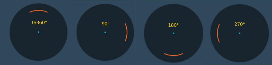
Set TIRF Angle, the azimuthal direction, in degrees, at which the illumination pattern starts. The diagram displays the resulting laser position, or arc, on the calibrated circle.
Note
Usefull for segmental and orbital TIRF.
-
Set TIRF Penetration Depth, the distance between the laser and the optical axis, expressed as a percentage of the calibrated TIRF circle radius:
- 100: the laser lies on the calibrated circle (TIRF).
- Intermediate values: the incidence angle is below the critical angle (HILO).
- 0: the laser is centered on the optical axis (epifluorescence).
Note
For the TIRF mode, the Penetration Depth value can be from 90 to 100.
Also set the excitation laser power, the filters, as for any other channel. Depending on the hardware configuration.
Click Add to keep the channel for the current session, or Save to store it permanently in the database. See Creating and Loading Channels.
Note
TIRF Mode, TIRF Angle, and TIRF Penetration Depth are stored in the channel. Different channels can therefore use different illumination regimes, for example a TIRF channel and a HILO channel for the same laser line.
Sequence Acquisition
To acquire TIRF images in a multidimensional sequence, select the saved TIRF channel in the Channel dimension. TIRF channels can be combined with widefield or other channels in the same sequence. The software applies the calibration and the TIRF parameters of each channel automatically when it switches channels.