Connections setup
This stage is the link between the devices and the Device Controller (DC).
-
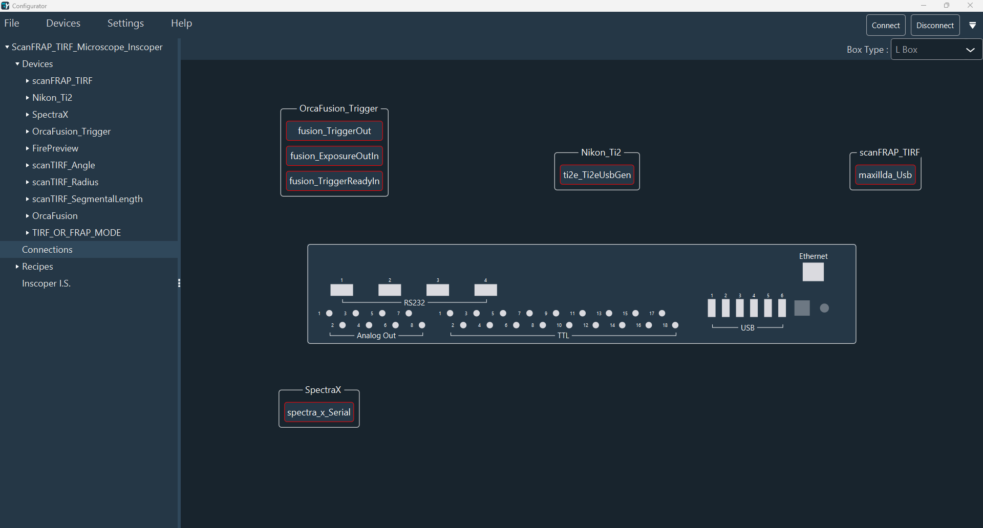
Click Connections inside the Configuration section,
you'll get a view of the box and the devices that need to be connected to the
DC.
-
The box type (S, M, L, XL) is recognized automatically. To select the box type
manually, click on the Box Type drop-down menu in the top
right-hand corner.
The drawing is automatically updated according to your choice.
-
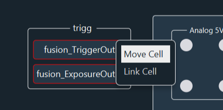
Indicate where you have connected your device to the DC: right-click on the
device you want to connect to change the mode from Move Cell
to Link Cell.
Notice:Move Cell button allows to move the device on the diagram.Fastpath:The box diagram can be moved by simple click on it.Fastpath:Click and hold the mouse down to move the entire diagram (box and devices).Fastpath:Zoom in and out with the mouse wheel.Fastpath:double click on the mouse wheel resets the size of the entire diagram.
-
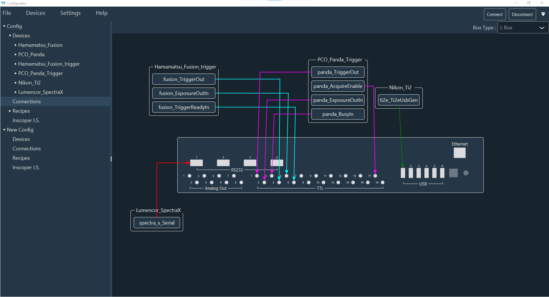
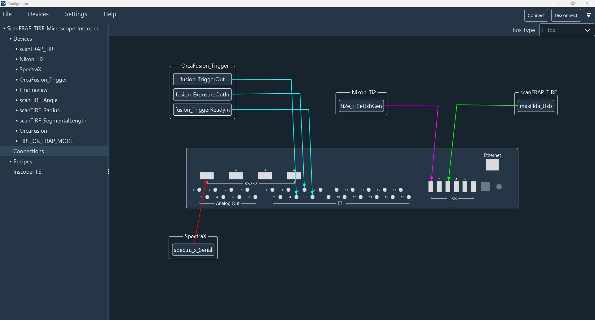
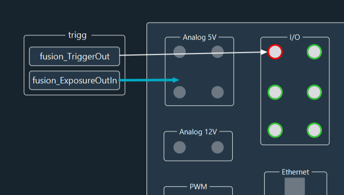
Link the connection by holding click from the connection to the DC. Repeat this
step for each connection
Note:The available ports for this connection are highlighted in green.When the connectors are occupied, it is surlight in red.
 Notice:Depending on the type of connection used, the connectors are automatically recognized. For example : the light source Lumencor Spectra X can be connected to the device controller by RS232 or USB connections.
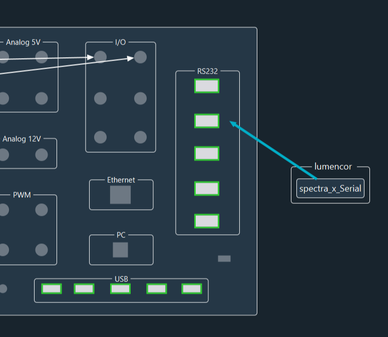 When the connections are linked to the device controller (DC), the colour of the box around the Sub Device name changes from red to white.
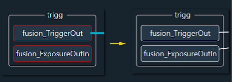
-
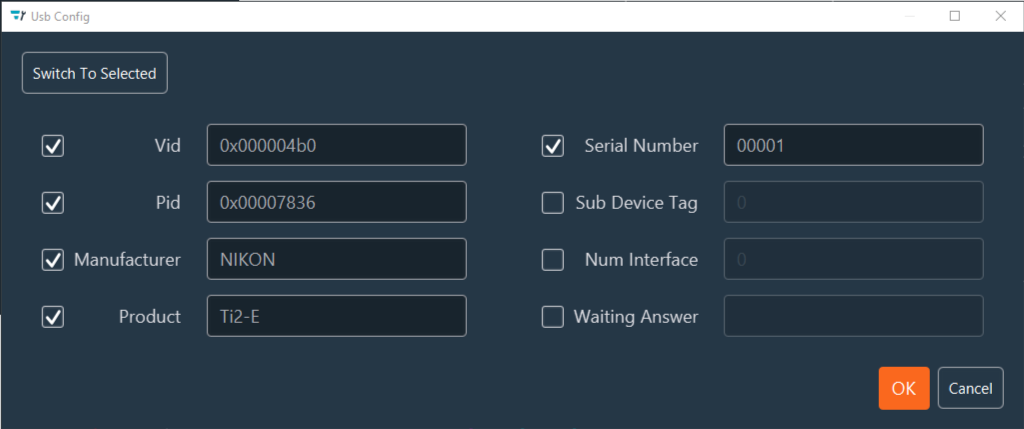
If the color of the box around the connection name is yellow, it means
that a parameter is missing. To change it, double-click the connection name. A
popup will appear and you can fill in the empty field. For example, for the
Microscope Stand Ti2, you will get the window below and you need to enter
the Pid and Vid numbers by checking the box of them.
-
You can also detect all connected devices and select which port you need.
Switch To Manual and Switch
To Selected
By clicking on Rest Usb View, The box will rescan all USB-connected devices.
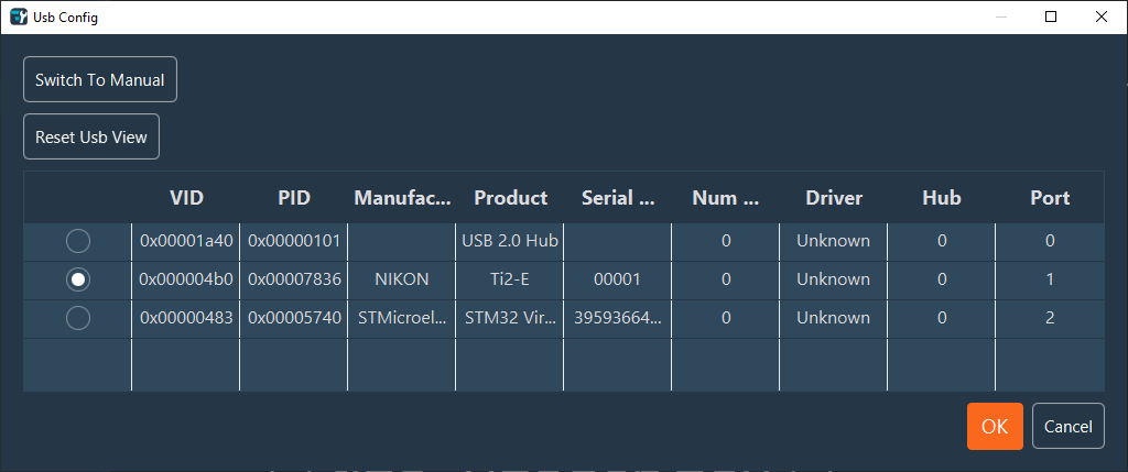 Note:In the list of USB ports, the first line corresponds to the USB hub inside the box (not valid for S type box). This is given for information only, to check that the box is working correctly.
 -
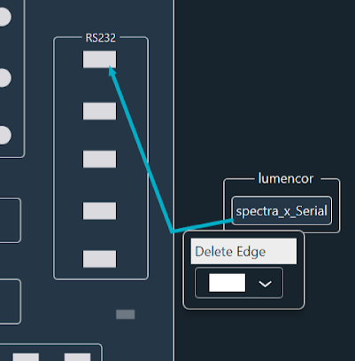
You can modify the color of the arrow (Color Box) or
delete it (Delete Edge) by a right click on it. If you
click on the arrow you create a spot and you can move it to make an angle (like
the example). To delete it, make a right click on the spot.