Pre-configuring the Inscoper Imaging Software
Once the recipe is generated, the final step is to design the user interface (Inscoper I.S.) used to control the system. This step allows for the customization of the layout, controls, and available options for acquisition workflows.
Review up to six configuration tabs to configure Inscoper I.S.:
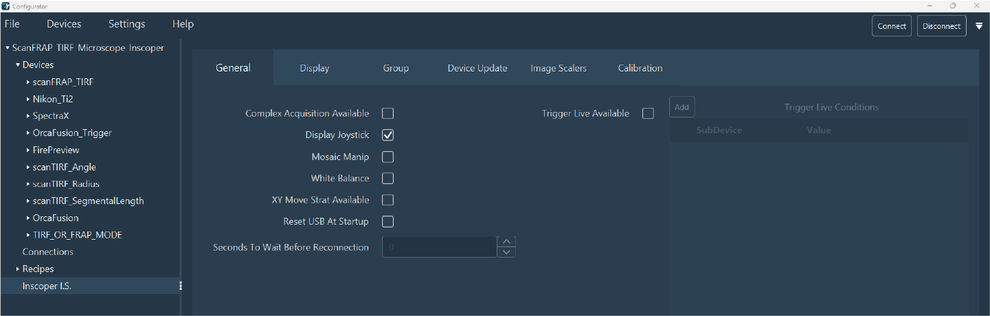
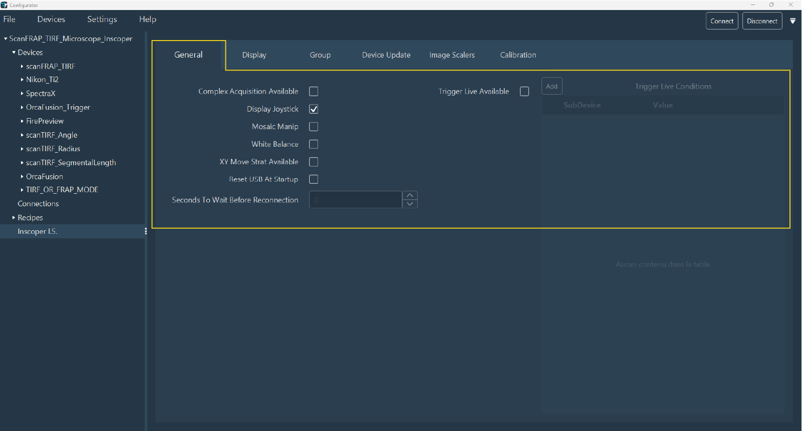
General
Use the General tab to select global elements or interface options:
- Complex Acquisition Available: Enable the creation of multi-dimensional acquisition sequences.
- Display Joystick: Add a virtual joystick with directional arrows for stage control.
- Mosaic Manip: Tiling calibration and experiment options.
- White Balance: Use if the system includes a color camera.
- XY Move Strat Available: Advanced stage movement options for optimizing travel between distant positions.
- Reset USB At Startup: Force a scan of all connected USB devices at startup (required for some devices to be detected).
- Seconds To Wait Before Reconnection: Specify the delay between rescanning and reconnection (useful for slow-initializing devices).
- Trigger Live Available: Synchronize the "Live" mode with another device via a DC sequence. Required for constrained image capture setups. Enabling this option activates Trigger Live Conditions.
Display
Use the Display tab to configure the interface layout. Organize controls into different sections (Location) and categories (Category).
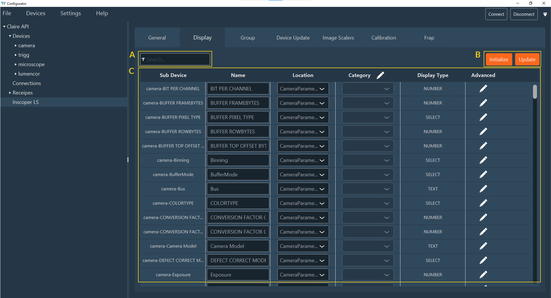
Key elements of this tab include:
- (A) Search Field: For quickly locating sub-devices.
- (B) Action Buttons: For interacting with the list (Initialize, Update).
- (C) Display Setting Table: The main configuration area.
1. Initialization
Click Initialize to generate all Display Data.
- Note: If initialization has been completed but new devices were added, click Update.
- Warning: Re-initializing overwrites any existing custom display settings.
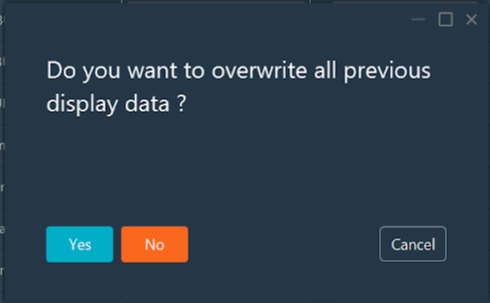
Table Columns
After initialization, the table displays the following for each sub-device:
- Sub Device: The sub-device bound to the display element.
- Name: The default label shown in the interface.
- Location: The section of the UI where the element appears (e.g., Setting, Channel, CameraParameters).
- Category: A sub-grouping within the Location.
- Display type: The type of UI control (e.g., Switcher, Slider). Generated by default; modifiable through customization.
- Advanced: Access to detailed parameters.
2. Modification
Modify parameters directly in the table:
- Name: Click and type to rename the element.
-
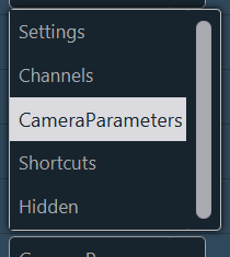
Location: Select a new location from the drop-down menu. Common locations include Setting, Channel, Shortcut, CameraParameters, and Hidden.
-
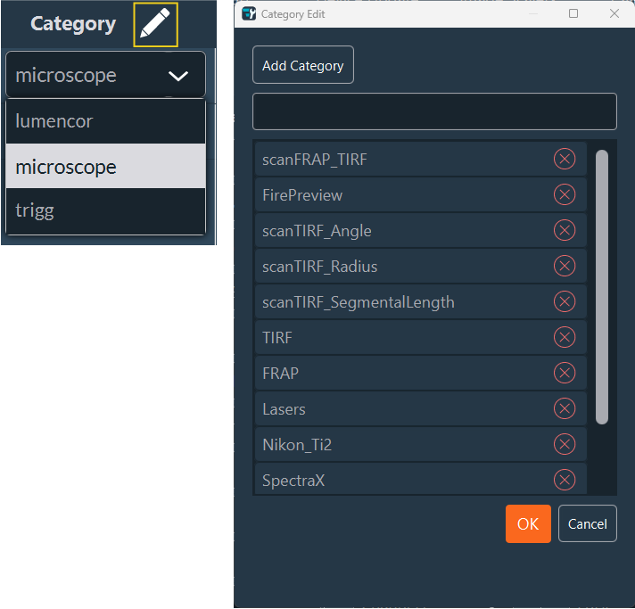
Category: Click the Edit (pen) icon to add a new category. Enter the name, click Add Category, and click OK. The new category then appears in the drop-down menu.
-
Display Type: Modify the UI control type by clicking Advanced parameters.
3. Advanced Settings
The Advanced tab aggregates all display parameters. Click the Edit (pen) icon for a sub-device to access three scrollable sections:
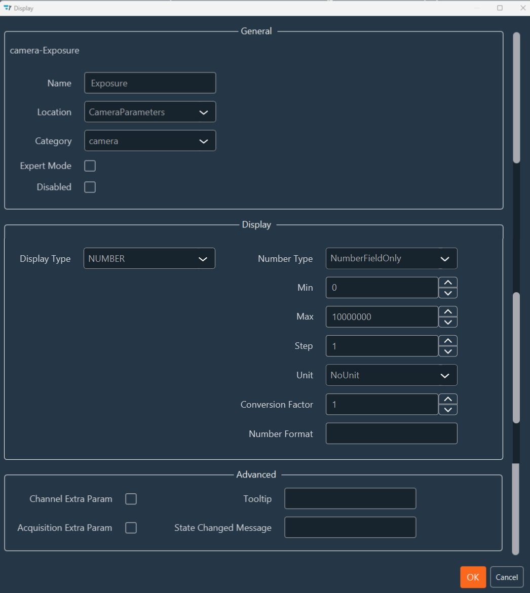
a. General
- Name, Location, Category: Standard identification fields.
- Expert Mode: Select this checkbox to hide the parameter in standard User Mode. Expert Mode grants unrestricted access, while User Mode provides a streamlined interface.
- Disabled: Prevents modifying the setting in the UI.
b. Display Type
Select the appropriate control type for the device property:
-
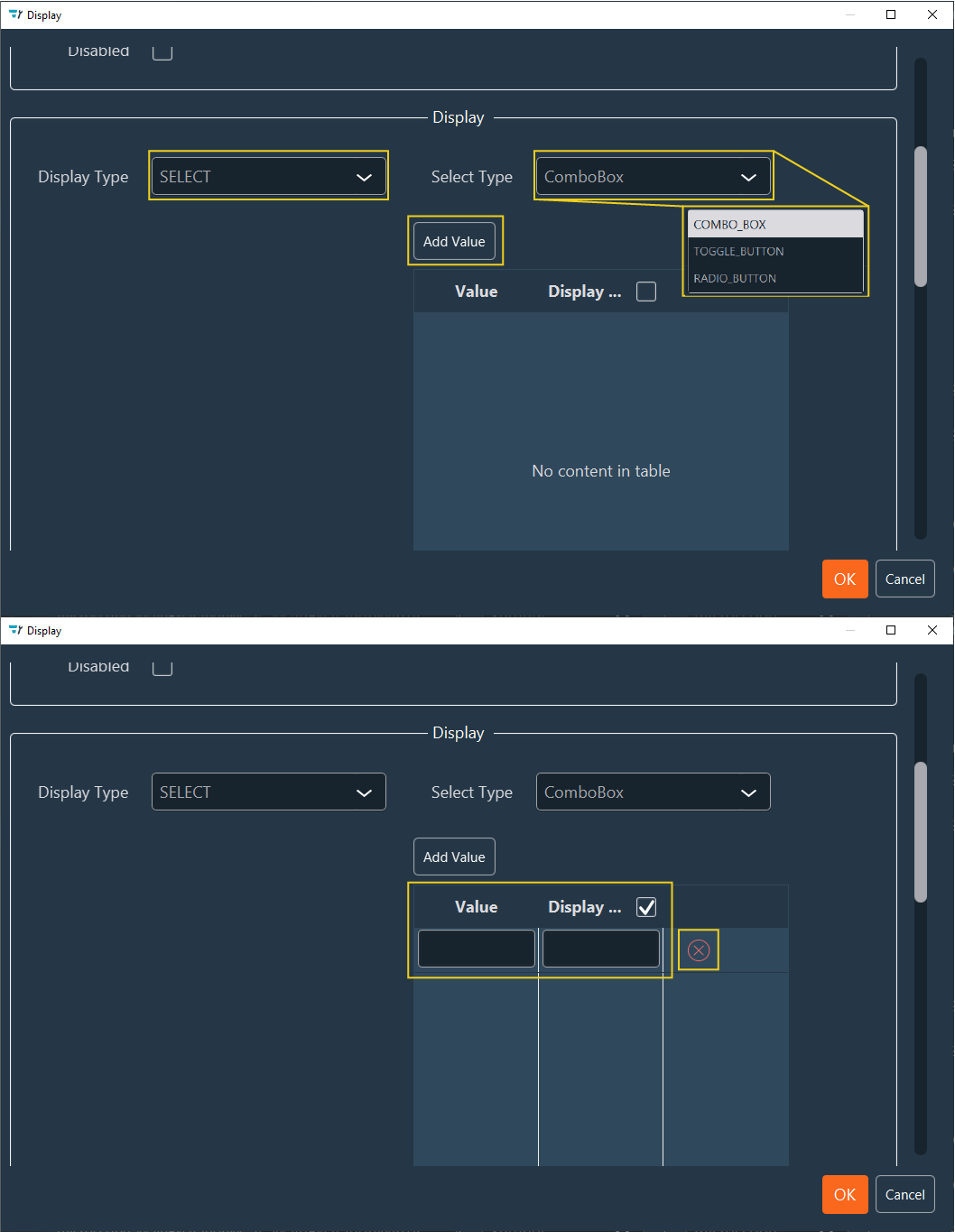
SELECT: Choose from Combo_Box (drop-down), Toggle_Button (2-state switch), or Radio_Button (multi-choice).
- Click Add Value to define options.
- Use the red cross to remove values.
Filter Wheel Configuration
For a 5-position filter wheel (indices 0–4), configure a SELECT / Combo_Box with these values:
Value Display 0 DAPI 1 GFP 2 YFP 3 Cy3 4 Cy5 -
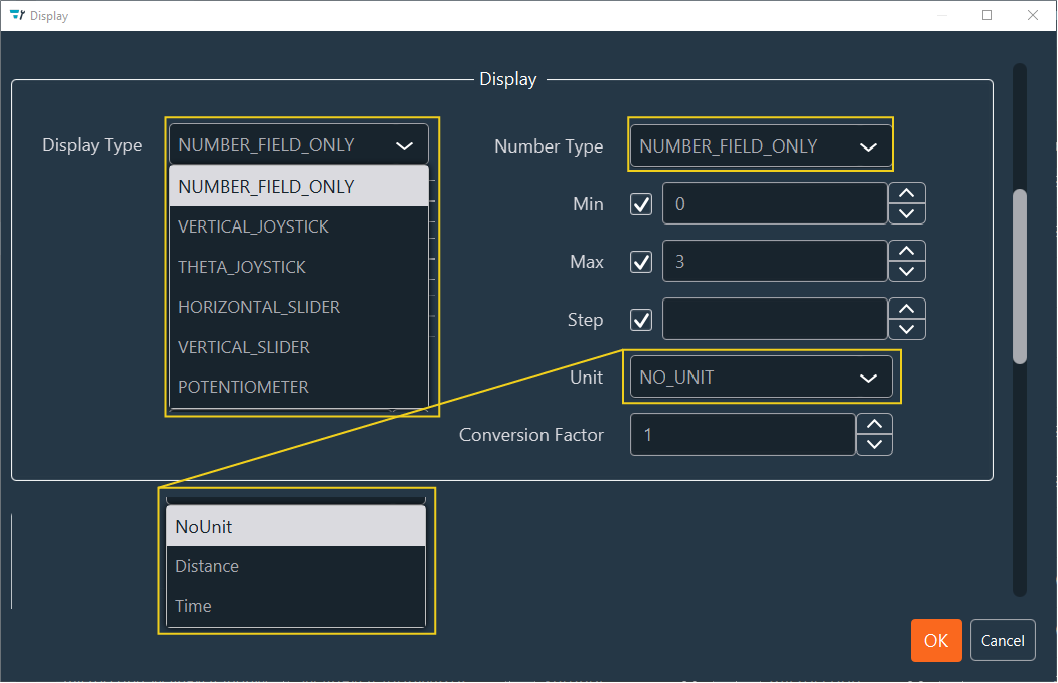
NUMBER: Choose from Number field, VerticalJoystick, ThetaJoystick, Horizontal/Vertical Slider, or Potentiometer.
- Required configurations: Min/Max Value, Step, Unit (Distance, Time, None), Format (decimal precision), and Conversion Factor.
Stage Control
Commonly used for stage movement controls.
-
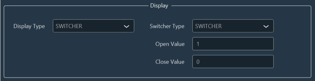
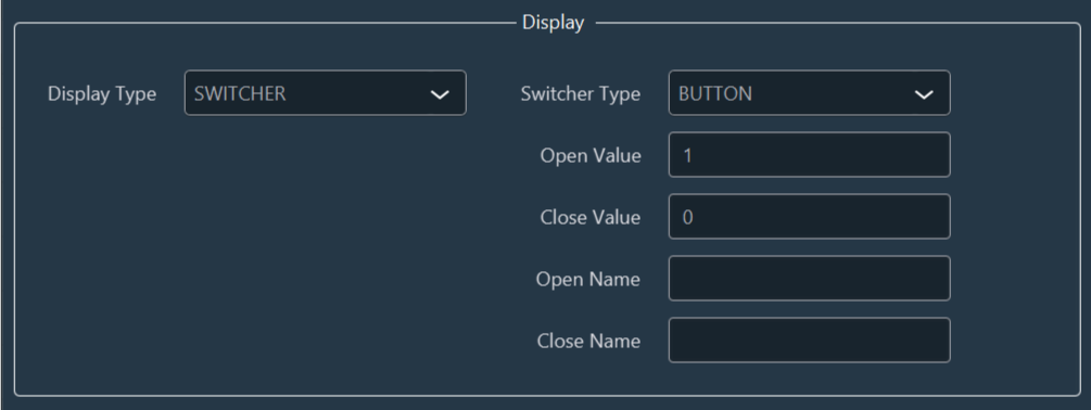
SWITCHER: Choose between Switcher or Button.
- Define the Open and Close values associated with the state change.
- For a Button, specify the open and close values and their respective display names.
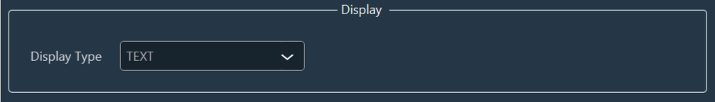
-
TEXT: The text display type requires no further action.
Group
Use this tab to group the display of multiple settings.
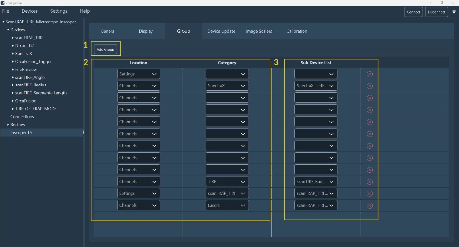
- Click Add group.
- Filter the sub-devices by Location and Category.
- Select the required sub-devices from the Sub Devices drop-down list.
- Repeat these steps if multiple groups are needed. Delete a group by clicking Delete (red cross).
Device Update
Use this tab to select devices for automatic value updates. The interface queries the drivers (DC, custom, and Micro-Manager) to update device values.
Example
Updating values is necessary when moving the stage manually via a joystick.
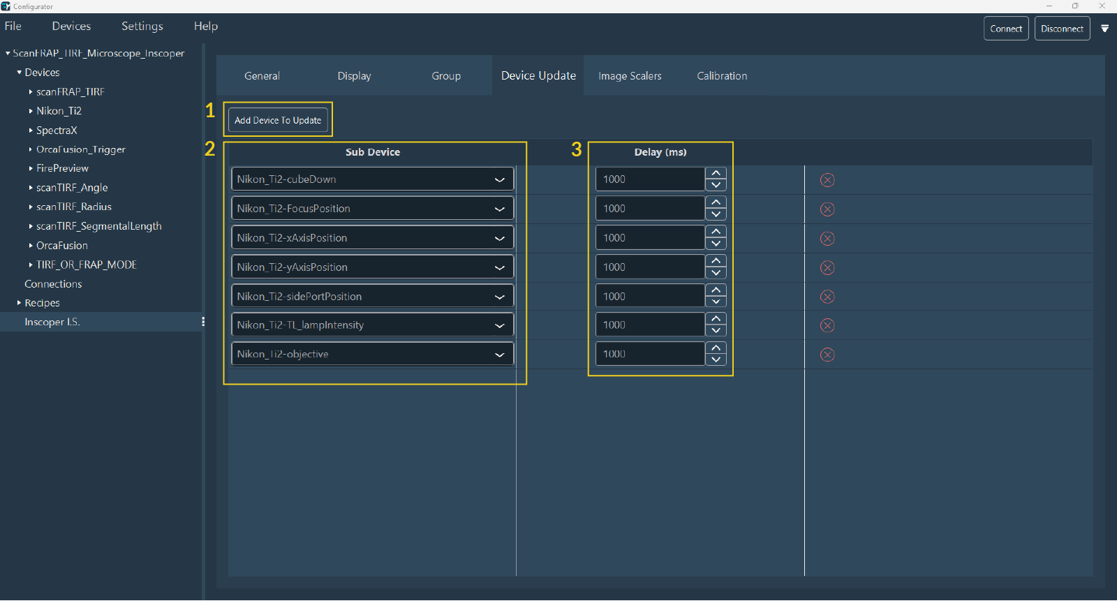
- Click Add Device to Update.
- Use the search form to select the required devices.
- Specify the update delay.
- Repeat these steps as needed.
- Delete a device by clicking Delete (red cross).
Image Scalers
Specify all devices that alter the image pixel size (e.g., objectives) in this tab.
Correct specification is critical for tile calibration, experiment workflows, scale bars, and metadata.
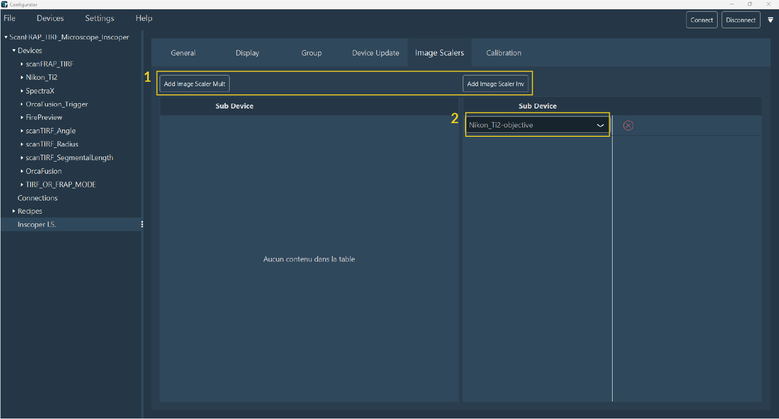
- Click Add Image Scaler Mult or Add Image Scaler Inv to specify the sub-device that enlarges or reduces the image size, respectively.
- Select the sub-device from the drop-down menu.
- Repeat these steps as needed.
- Click Delete (red cross) to remove the sub-device.
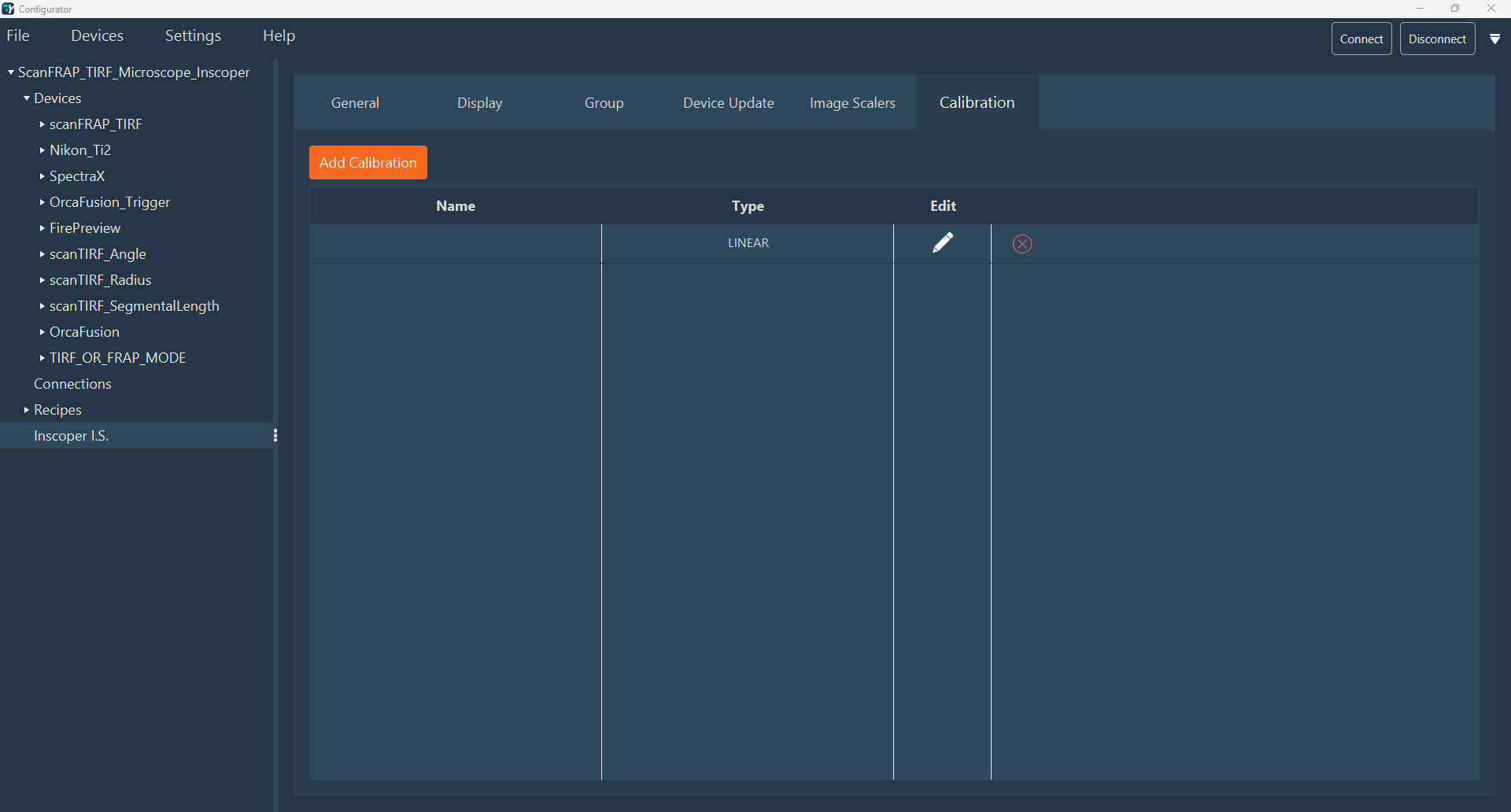
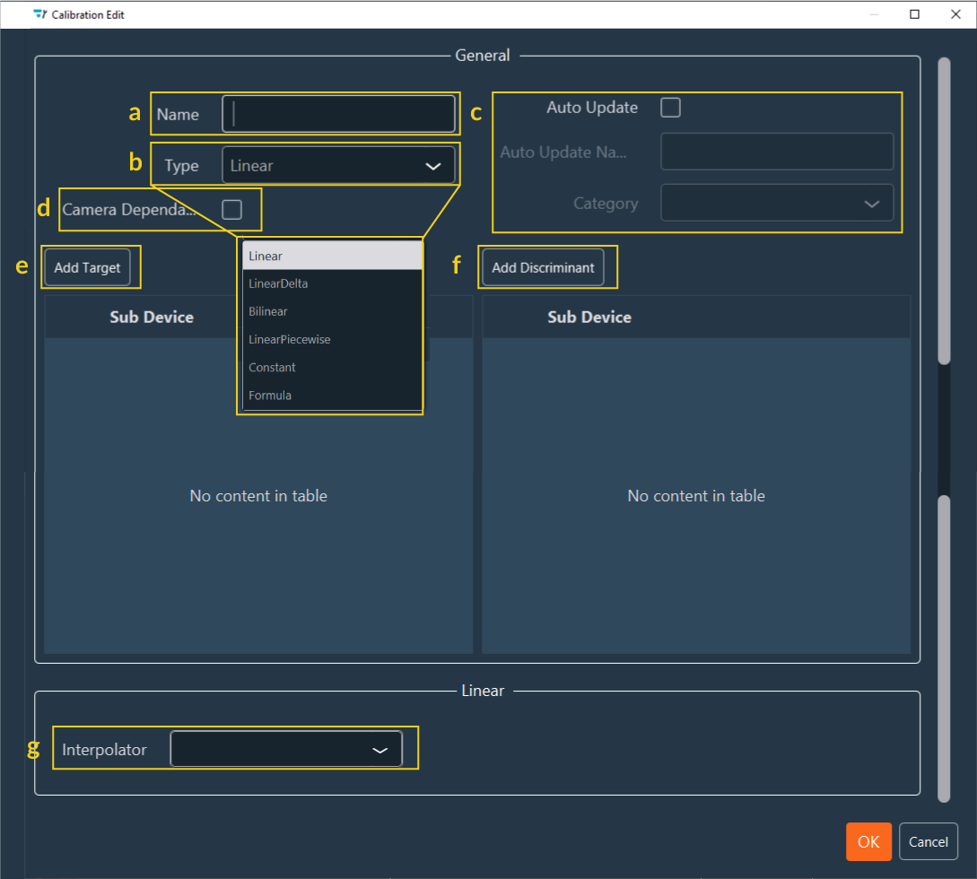
Calibration
Calibration establishes a dependency link between two sub-devices, enabling various application-specific setups.
- Click Add Calibration to create a new entry.
-
Edit an entry by clicking the Edit (pen) icon or delete it using the Delete (red cross) icon.
-
Configure the following in the Calibration Edit window:
-
Specify the calibration Name.
-
Select the Type of calibration (the formula used for device movement). Available types include:
Linear: Linear formula (ax+b).Linear delta: Delta-based linear formula.Bilinear: Representing a 3D plane (ax+by+c).Linear piece wise: Piecewise linear approximation.Constant: Fixed parameter between two devices.Formula: Custom user-defined formula.
-
Auto Update: Selecting this checkbox adds a button to the interface for deactivating the calibration. If selected, specify the button Name and its Location (Category).
-
Camera Dependant: Select this checkbox if the calibration is camera-dependent (e.g., Tiling and FRAP).
-
Add Target: Add the target device to be modified.
-
Add discriminant: A discriminant is a sub-device or device that, when modified, requires recalibration. For example, in FRAP calibration, changing an objective or filter necessitates a new calibration.
Note
Discriminants typically include filters and objectives.
-
Interpolator: Select the sub-device other than the objective. For example, the Bilinear formula requires two interpolators.
-
-
Click OK to save the calibration.
The interface is now tailored to the specific experimental requirements. Launch the Inscoper Imaging Software to verify the layout and begin acquisitions.