Setting up Connections
The Connections stage establishes the logical link between configured devices and the physical ports on the Device Controller (DC). This mapping ensures the software sends commands to the correct hardware interfaces.
Accessing the Connections View
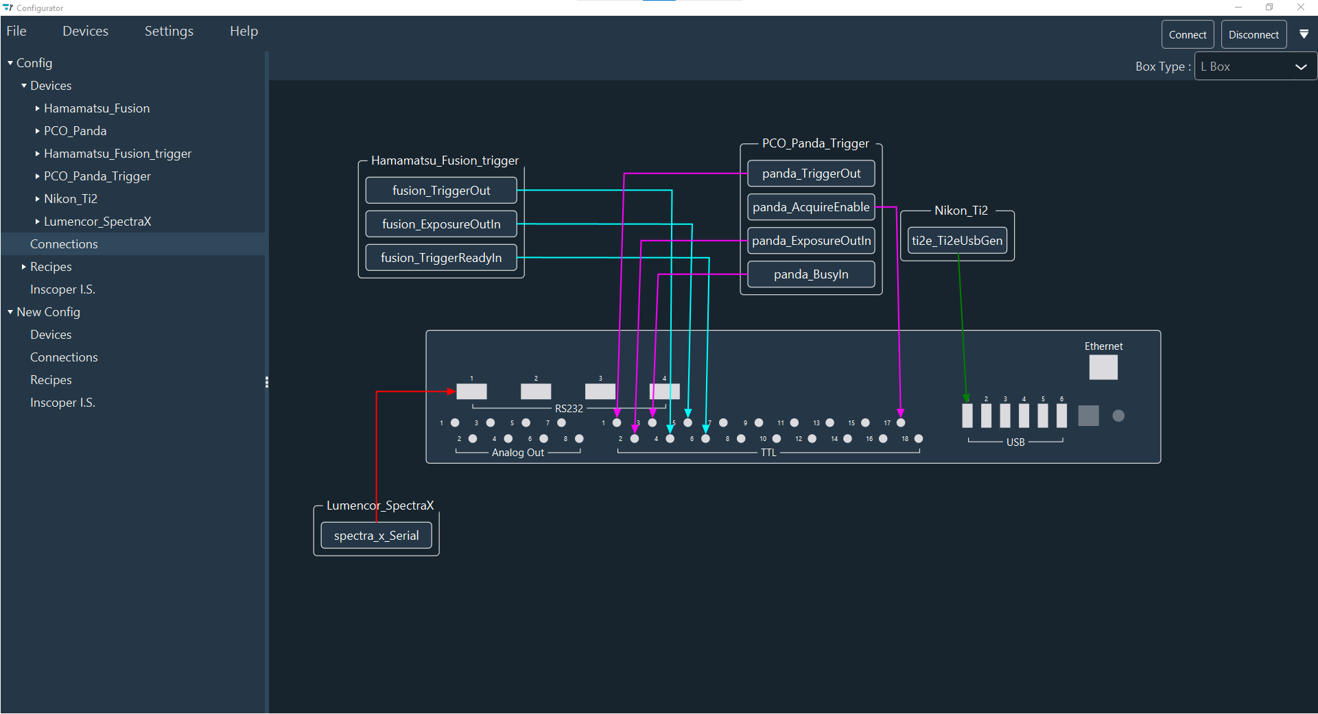
Click Connections in the Configuration section to view the controller and the devices requiring connection.
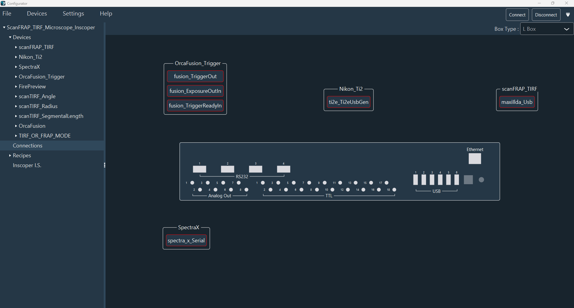
Defining the Box Type
The system automatically detects the box type (S, M, L, or XL). To override this selection manually:
- Use the Box Type drop-down menu in the top-right corner.
- The diagram updates automatically to reflect the port layout of the selected model.
Managing the Diagram
Organize the workspace to facilitate easier connections before linking ports. Use the following controls to navigate the diagram:
| Action | Control |
|---|---|
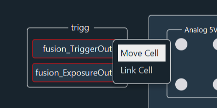
| Move Device | Ensure the device is in Move Cell mode (right-click to toggle). |
| Move Box | Click and drag the DC box diagram. |
| Pan Workspace | Click and hold the mouse button on the background to move the entire diagram. |
| Zoom | Use the scroll wheel to zoom in and out. |
| Reset View | Double-click the scroll wheel to reset the zoom and center the diagram. |
Linking Devices to the DC
To create a physical link between a device and the controller:
- Right-click the device and switch from Move Cell to Link Cell mode.
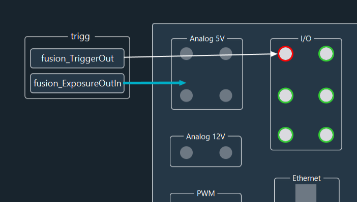
- Click and hold the connection point of the device, then drag the line to the target port on the DC.
- Repeat this process for all device connections.
Port Highlighting
Available ports are highlighted in green. Occupied connectors are highlighted in red.
Automatic Recognition
Connectors are automatically recognized based on the connection type. For example, the Lumencor Spectra X light source connects to the Device Controller via RS232 or USB.
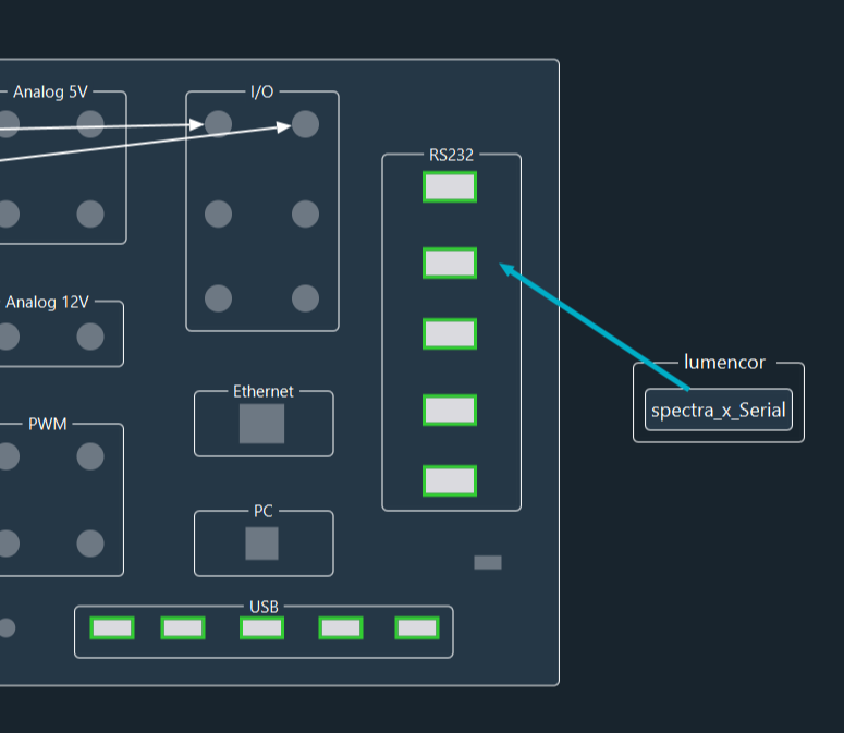
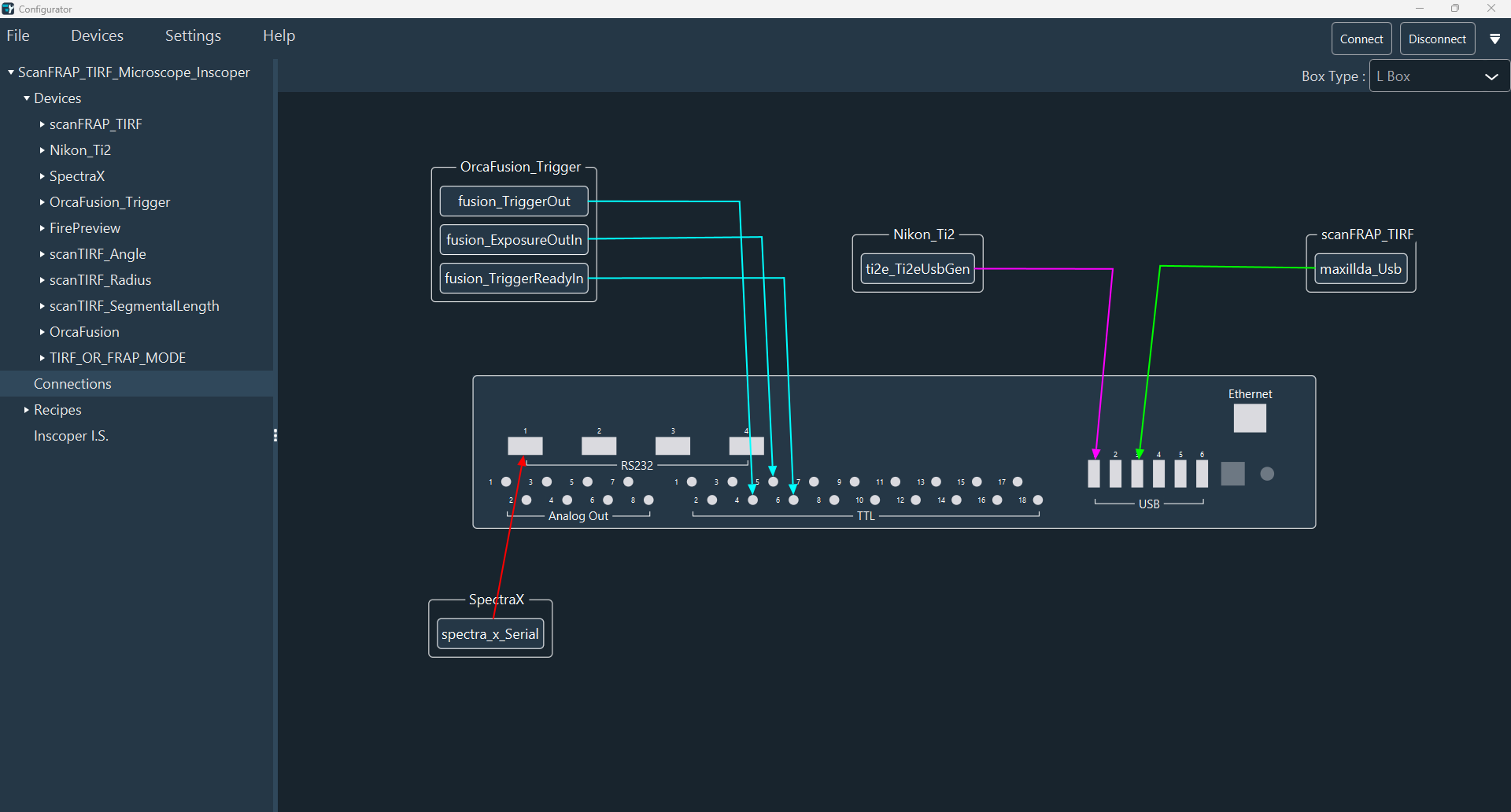
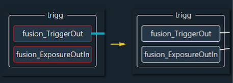
Connection Status: When a connection is successfully linked, the border surrounding the sub-device name changes from Red to White.
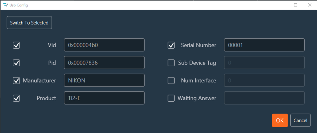
Handling Missing Parameters
If a connection box appears Yellow, required communication parameters (e.g., PID/VID numbers) are missing.
- Double-click the connection name.
- In the popup window, fill in the required fields. For a Microscope Stand Ti2, select the checkboxes for Pid and Vid to enable auto-detection, or enter them manually.
USB Detection and Management
Automate port assignment or refresh the hardware view using the USB management tools:
- Reset USB View: Triggers a scan of all connected USB hardware.
- Switch To Manual / Switch To Selected: Grants granular, manual control over port assignments if automatic detection is insufficient.
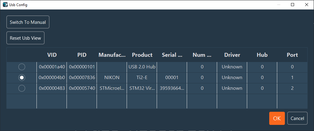
USB Hub Info
The first line in the USB port list typically represents the internal USB hub of the box (except for Type S). This line is used for diagnostic purposes to ensure internal communication is functional.
Customizing the Diagram
To improve the readability of complex diagrams:
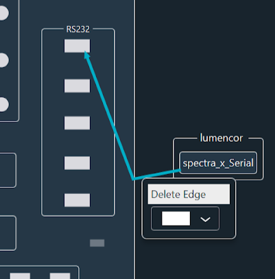
- Adjust Lines: Click a connection arrow to create an anchor point. Drag the anchor point to create logical angles and route cables clearly.
- Remove Angles: Right-click an anchor point to delete it.
- Styling: Right-click an arrow to change the Color Box for visual separation, or select Delete Edge to remove the connection.
Once all devices are correctly linked, the diagram displays all devices with white borders, indicating valid connections.
All logical devices are now physically mapped to the controller. Proceed to the next step: defining acquisition recipes.