Generating Recipes
Automatic Recipe Creation
This section guides you through the automated generation of standard recipes derived from your device configuration. Completing this step ensures that all core microscope functions are correctly mapped and ready for operation.
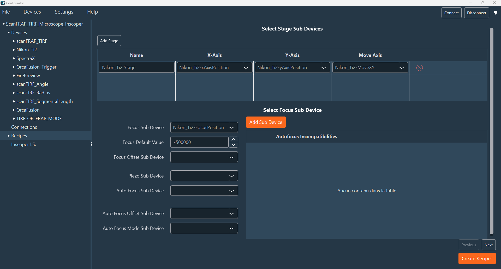
- After configuring and connecting your devices, navigate to the Recipes tab on the left sidebar. Verify that the correct sub-device is assigned to each function (e.g., Stage X, Stage Y, Focus). While these fields are pre-filled, you must confirm that they accurately reflect your current configuration.
- In the Select Stage Sub Devices section, a table defines the components (X, Y, Move) for each stage. Enter a descriptive name for the stage and map the appropriate sub-device for each row. You can add new stages using Add Stage or remove them using the Red Cross.
-
Configure the focus device properties, including any piezo or autofocus sub-devices. Click Next to proceed.
-
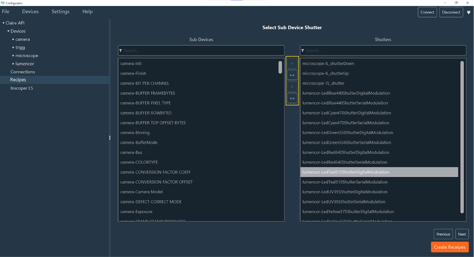
Configure the shutter list. The panel on the right displays the shutter sub-devices currently identified in your configuration. Review this list carefully: add any missing shutters from the available list on the left, and remove any incorrect entries (false positives). Ensure that the right-hand list contains all and only the valid shutter sub-devices for your system. Use the arrow buttons to move items between the lists:
- >>: Move all sub-devices to the shutters list (Right).
- >: Move only the selected sub-device to the shutters list (Right).
- <<: Remove all sub-devices from the shutters list.
- <: Remove only the selected sub-device from the shutters list.
Tip
Use the search bar to quickly locate specific elements.
Click Previous to return to the prior step. Once your shutter list is correct, click Next to continue.
-
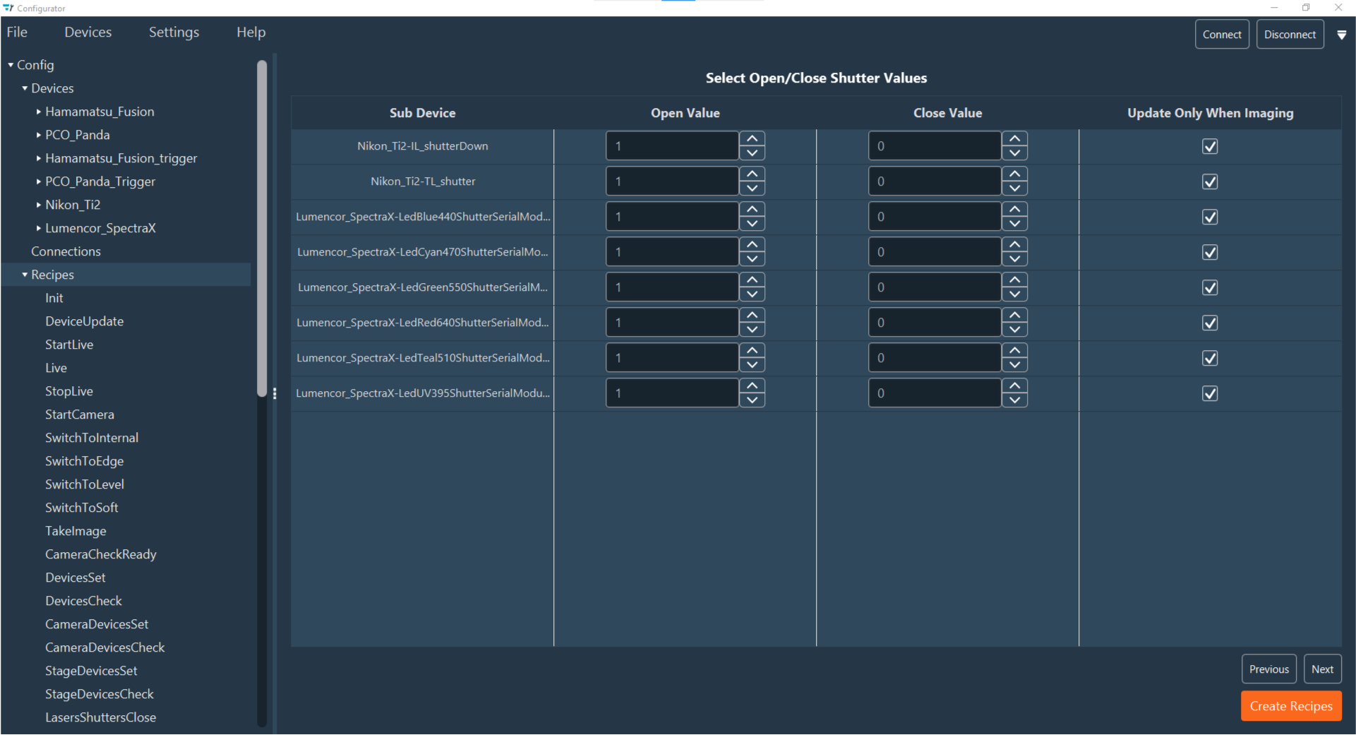
Verify the configuration for each shutter sub-device listed in the rows. For each shutter, check the columns:
- Open Value: Enter the value that opens the shutter (typically 1).
- Close Value: Enter the value that closes the shutter (typically 0).
- Update Only When Imaging: Check this box to restrict shutter status changes to Live or Acquisition modes only. Uncheck it to allow manual control of the shutter status at any time.
Note
Ensure you verify whether your hardware requires a 0 or 1 to open/close the shutter, as this can vary.
When verification is complete, click Next.
-
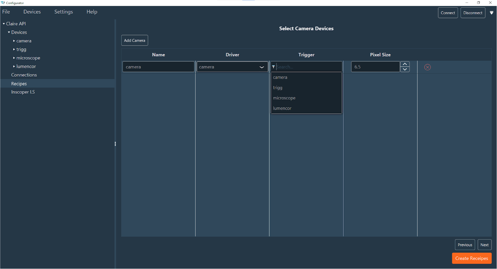
Configure your cameras. Detected cameras will appear automatically in the table, where each row represents a camera device. You can manually include additional cameras by clicking Add Camera or remove them using the Red Cross. For each camera row, specify the Name, Camera Driver, Trigger Device (optional), and Pixel Size. When finished, click Next.
-
Review the pre-filled sub-devices (
Start Acquisition,Stop Acquisition,Snap,Soft Trigger). These are sub-devices of the Camera Device. If a Trigger Device was selected in the previous step,Edge Trigger,Level Trigger, andCheck Readyfields will also be available. Click Next to proceed.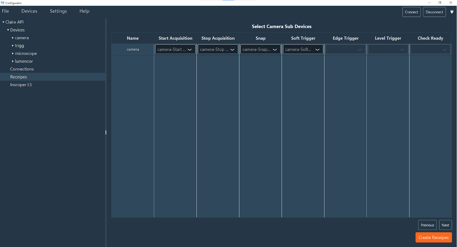
-
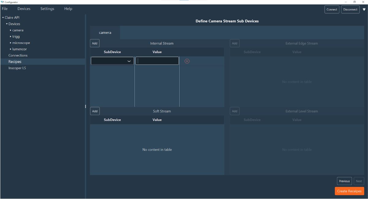
Define the Camera Stream parameters for different modes. This section contains four tables, one for each stream type. In each table, every row represents a sub-device and its corresponding value. You can add or remove rows using the Red Cross.
- Internal Stream: Configurations for Live or Snap modes.
- Soft Stream: Configurations for software-triggered modes (via
Soft Trigger). Available only if Soft Trigger was specified. - External Edge Stream: Configurations for DC-triggered modes via TTL (fixed exposure). Available only if Edge Trigger was specified.
- External Level Stream: Configurations for DC-triggered modes via TTL (variable exposure). Available only if Level Trigger was specified.
The specific sub-devices required depend on your camera model.
-
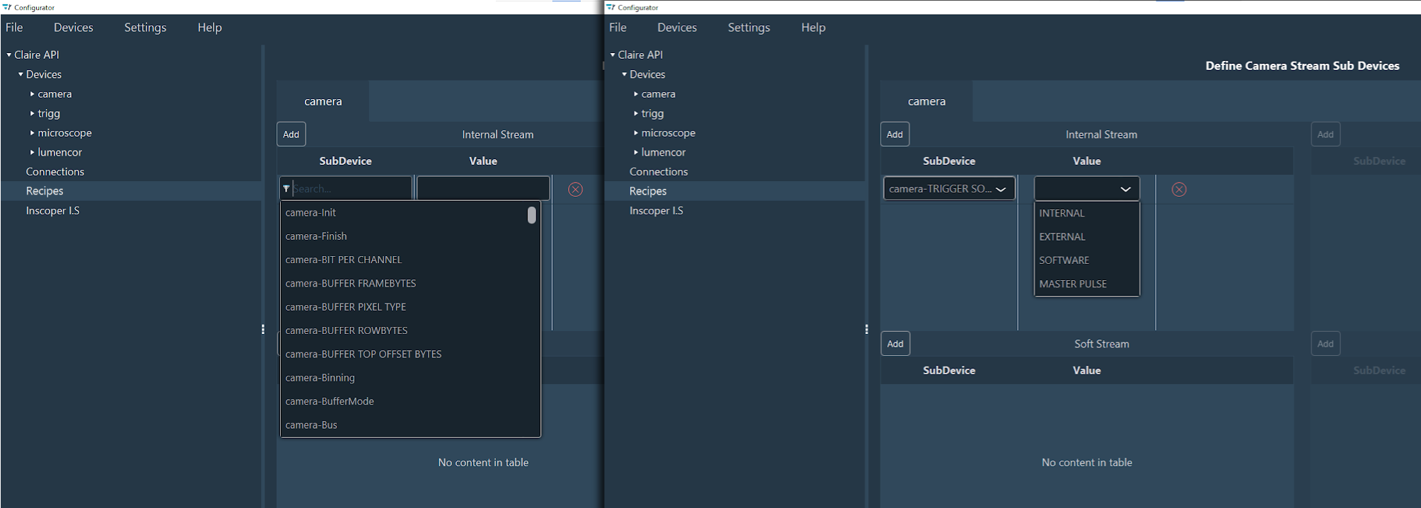
Select the appropriate Sub Device and Value for each field using the search box. Once selected, the specific values for that sub-device will appear in the Value drop-down menu.
-
(Optional) For systems using special techniques like FRAP or TIRF (via ILDA connector) or FLIM options, check the ILDA functions box.
-
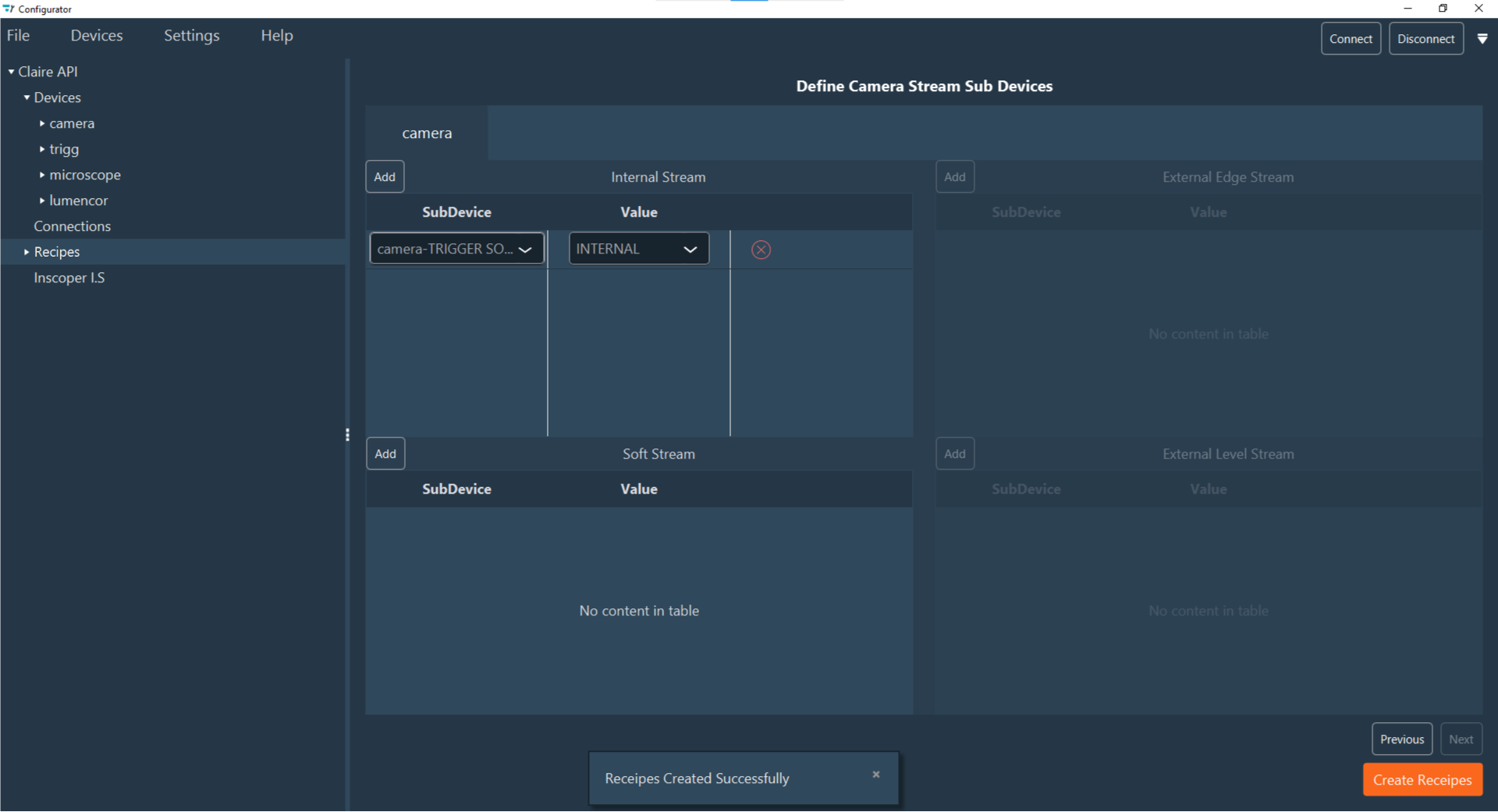
When all properties are configured, click the orange Create Recipe button at the bottom right corner. A confirmation popup "Recipes Created Successfully" will appear. The new recipe will then be listed as a sub-element under the Recipes section in the left-hand configuration menu. You can click these recipes to modify them if needed.
-
Typically, recipes do not require modification. However, you can drag and drop functions to reorder them if necessary.
The automatic generation is now complete, and your system is equipped with the essential recipes for standard usage. You may now review these recipes or proceed to add custom functions.
Manual Recipe Creation
For specific requirements beyond standard automation, this section explains how to manually create and configure custom recipes. This process provides precise control over individual sub-devices and acquisition sequences.
-
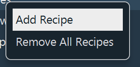
To add a new recipe, right-click the Recipes section in the left-hand configuration menu and select Add Recipe.
Note
To delete all existing recipes, select Remove All Recipes.
Note
To duplicate an existing recipe, click Duplicate, select the target configuration, enter a name for the new recipe, and validate.
-
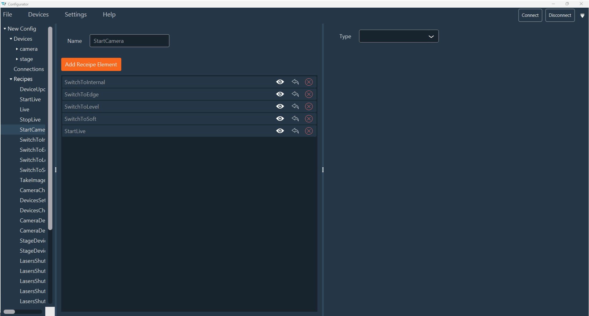
Enter a descriptive name for the recipe in the Name field.
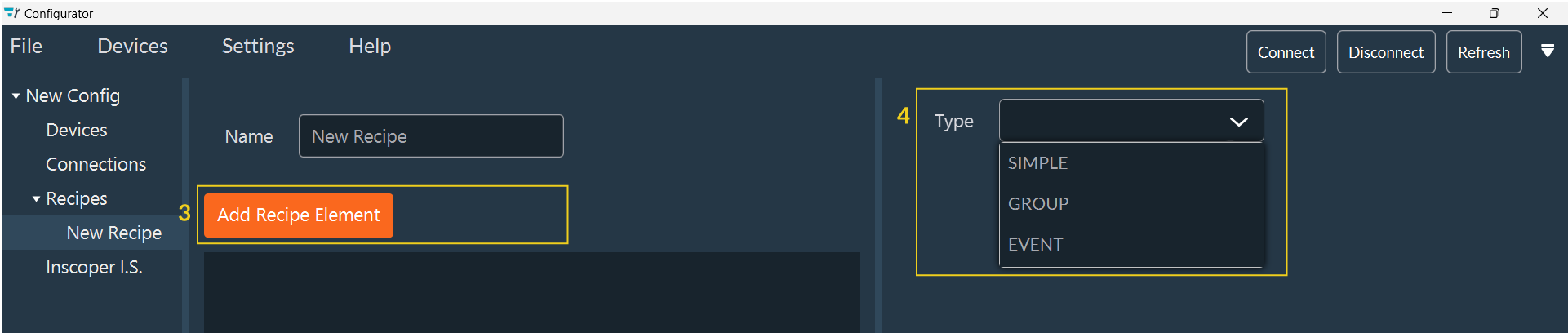
- Click Add Recipe Element to begin configuring the recipe.
-
Select the Type of recipe element:
- SIMPLE: A recipe for a single sub-device (or a list of sub-devices if a Recipe ID is selected).
- GROUP: A recipe that calls another recipe.
- EVENT: Triggers a specific action at a defined moment in the acquisition sequence (e.g., stop or pause). This is useful, for instance, to ensure shutters close when the system pauses. This type works for configurations with or without a Device Controller (DC).
-
If you select SIMPLE (5), configure the following options:
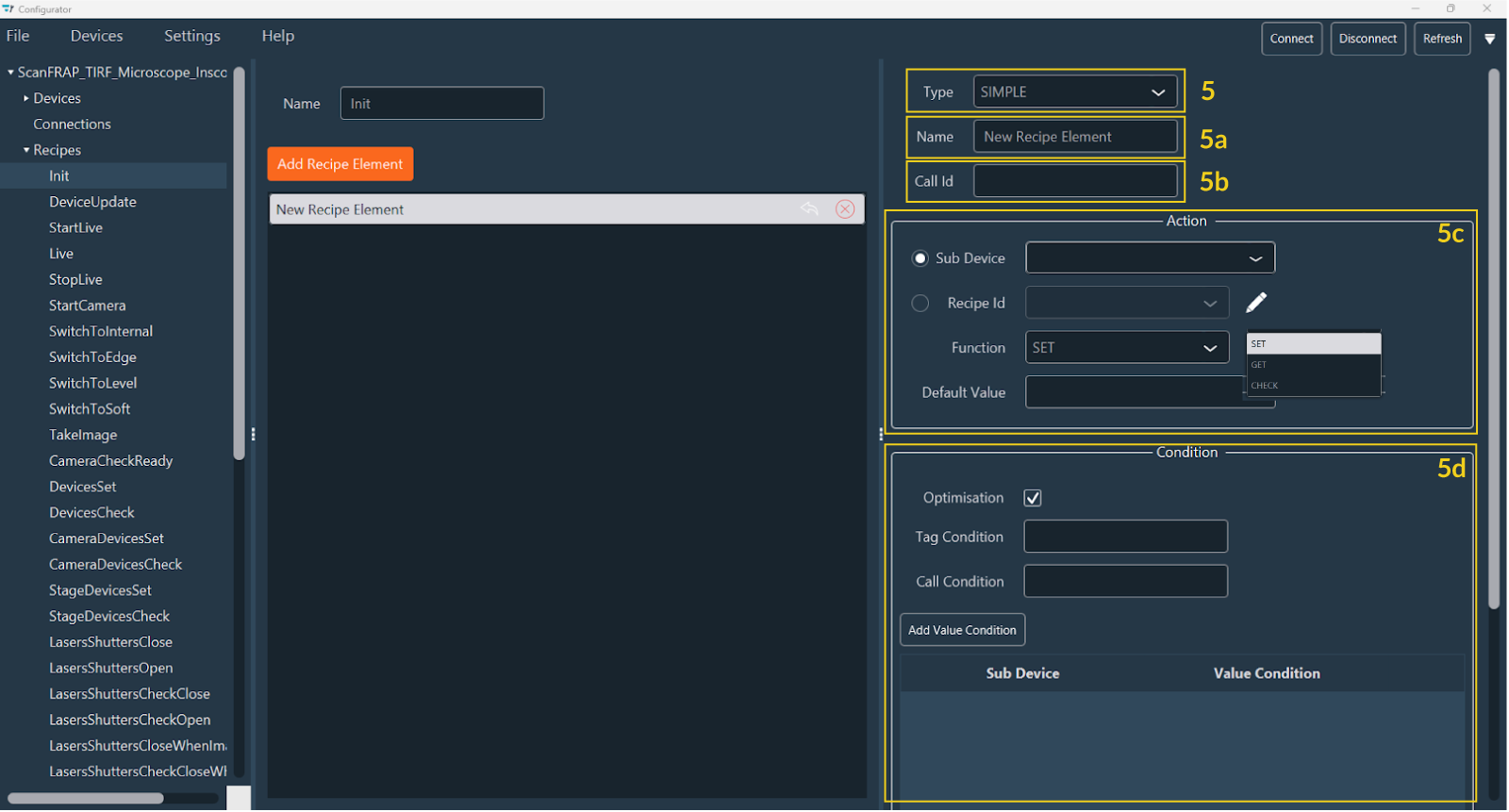
- Name (5a): Modify the name of the recipe element.
- Call ID (5b): Specify the unique ID for the recipe.
-
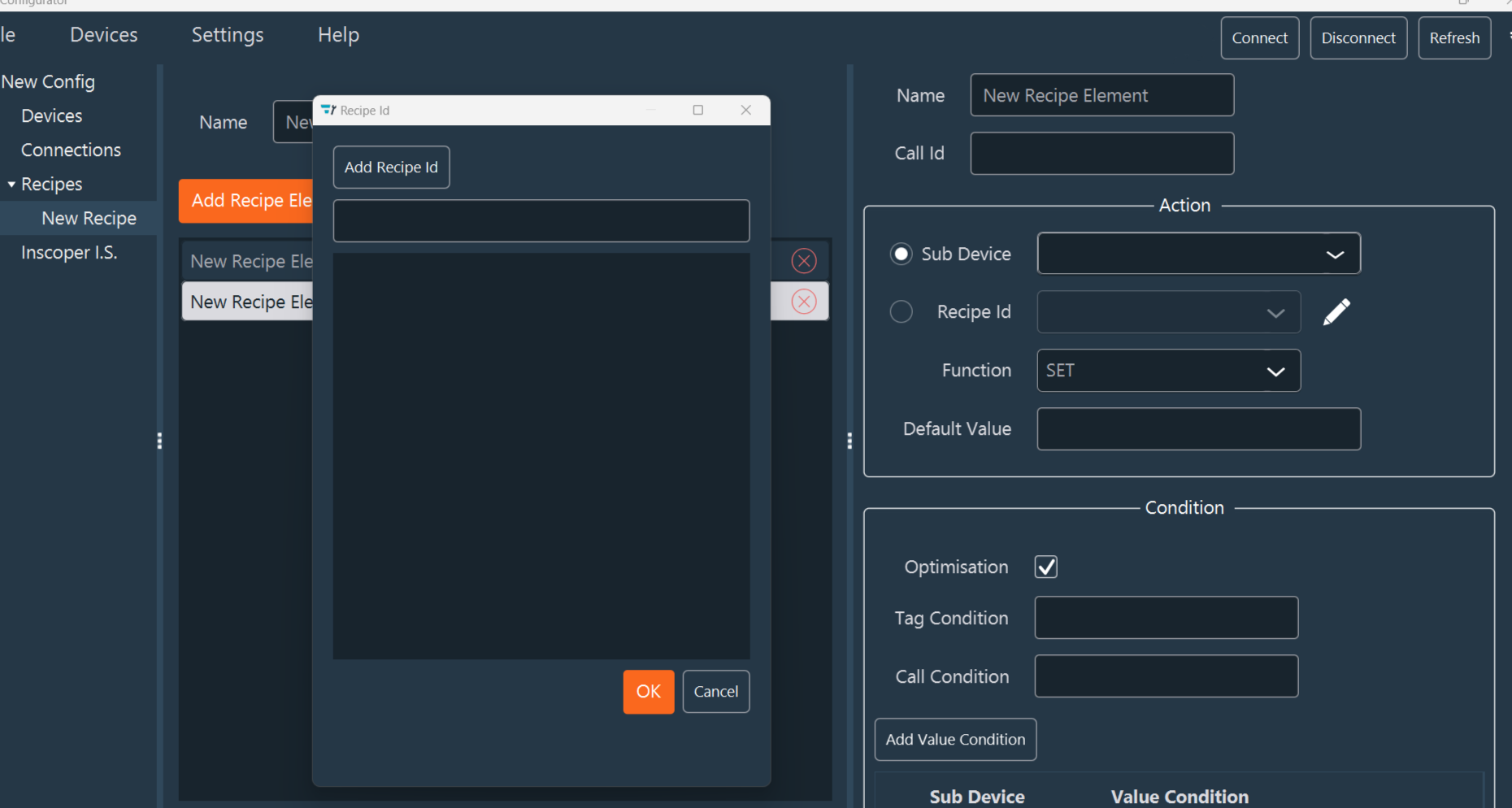
Action (5c):
- Sub Device / Recipe ID: specific the sub-device involved or the Recipe ID to be called. Click the pencil icon to open the Add Recipe ID popup.
Note
Recipe IDs created at the device level cannot be removed or modified. However, Recipe IDs created at the recipe level can be fully managed (created, modified, or deleted).
-
Function: Choose the function to execute:
- SET: Sends a value to the sub-device.
- GET: Retrieves the current value from the sub-device.
- CHECK: Waits until the sub-device reaches a specific status.
-
Default Value: Define a default value for the action.
-
Condition (5d):
- Optimisation: Check this box to execute the function only if the value has changed.
-
Tag and Call Condition:
- Tag Condition: A boolean expression based on the presence or absence of a specific tag.
- Call Condition: A boolean expression to check if a recipe element with a specific
CallIDhas been executed previously (e.g.,TI2xAxisPosition || TI2yAxisPosition).
-
Value Condition: Click Add Value Condition to add logical constraints.
- Select a sub-device and define its Value Condition.
- You can add multiple value conditions as needed.
-
If you select GROUP, you can include multiple recipe elements. Click Add Recipe Element and repeat the steps above to configure each one.
-
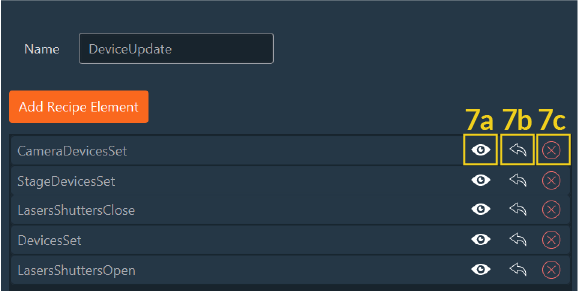
Use the recipe element tools to manage your configuration:
- a. View Details: View configuration details (valid only for GROUP elements).
- b. Move: Transfer the recipe element to another recipe.
- c. Delete: Remove the recipe element.
- d. Reposition: Drag and drop the recipe element to change its order in the list.
Your custom recipe is now fully configured and saved. It allows for tailored control of your system and can be utilized in your experimental workflows.
ILDA Functions for FRAP, TIRF, and FLIM Modules
If the system includes additional modules such as FRAP, TIRF, or FLIM, you must configure the ILDA functions.
-
In the ILDA Functions tab, select the device connected to the ILDA connector. Note: This option is only available for XL-type Device Controllers.
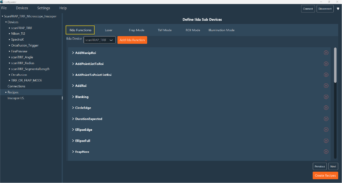
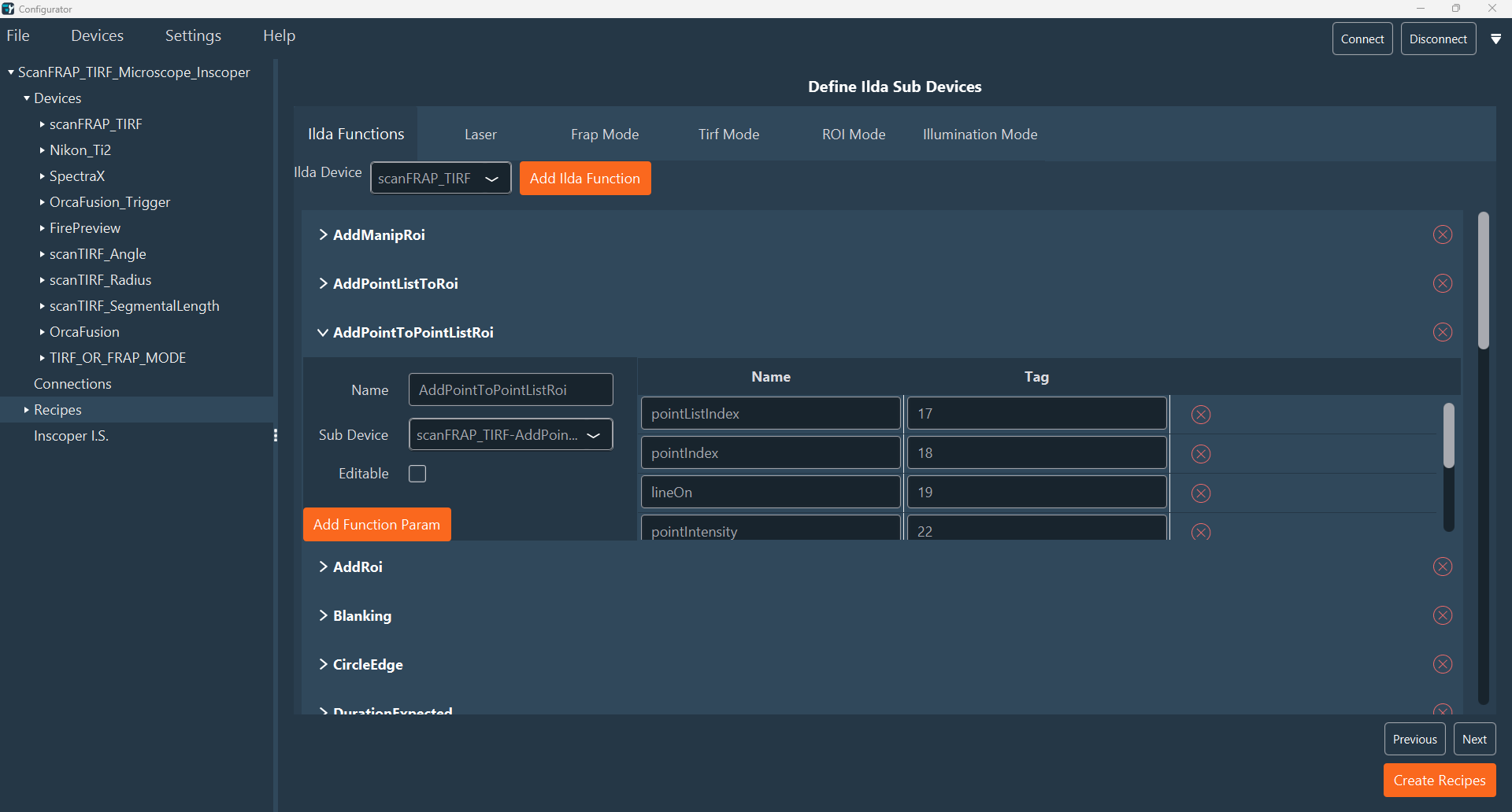
-
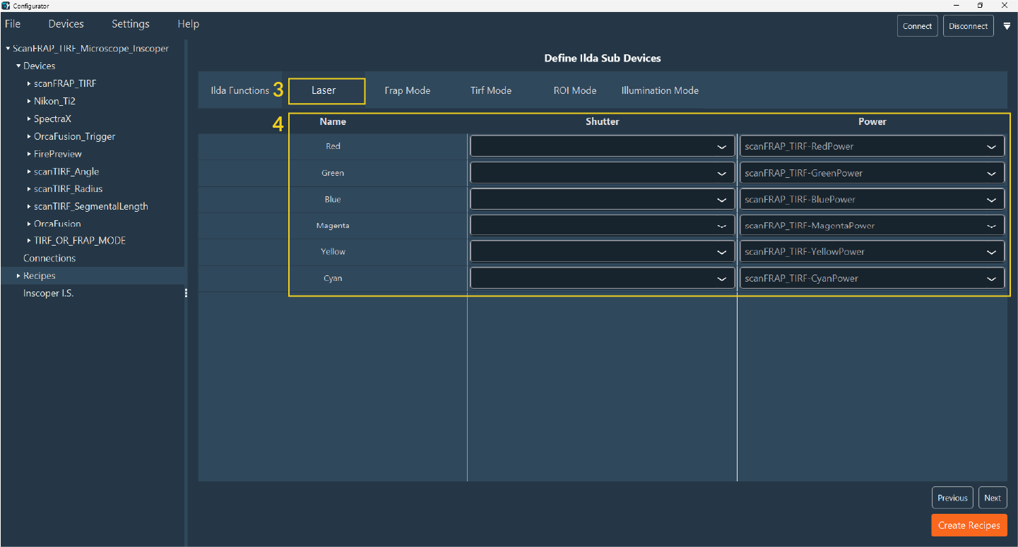
The system automatically loads all ILDA functions and their associated parameters. Verify that the functions and parameters are correct, then navigate to the Laser tab (3).
-
In the Laser tab (4), specify the shutter and power sub-devices for each laser line using the drop-down menus in the table.
-
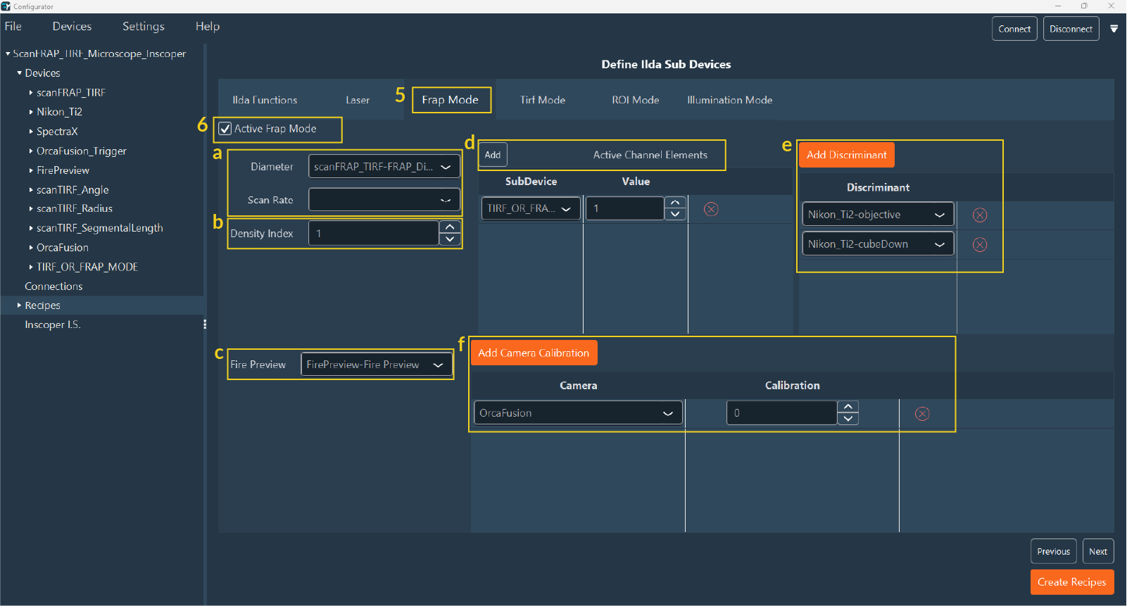
Navigate to the FRAP Mode tab (5) and select Active FRAP Mode to enable these options in the user interface (6).
- a. Select the sub-device that determines the FRAP density and scan rate.
- b. Specify the Density Index, which must match the FRAP diameter value defined for the sub-device in the Devices tab.
- c. Select the sub-device for the Fire Preview.
- d. Enable the Active Channel Elements shutter for FRAP to identify the FRAP channel.
- e. Add discriminants for FRAP calibration (e.g., Objective, Filter Cube).
-
f. Add the camera calibration.
Note
If using multiple cameras, specify whether to use a shared calibration or unique calibrations for each camera.
-
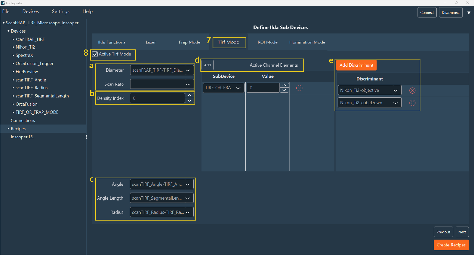
Navigate to the TIRF Mode tab (7) and select Active TIRF Mode (8):
- a. Select the sub-device assigned to the TIRF density.
- b. Specify the Density Index, matching the TIRF diameter set in the Devices tab.
- c. Select the sub-device responsible for Angle, Angle Length, and Radius.
- d. Enable the Active Channel Elements for TIRF.
- e. Add discriminants for TIRF calibration (e.g., Objective, Filter Cube, Lasers).
-
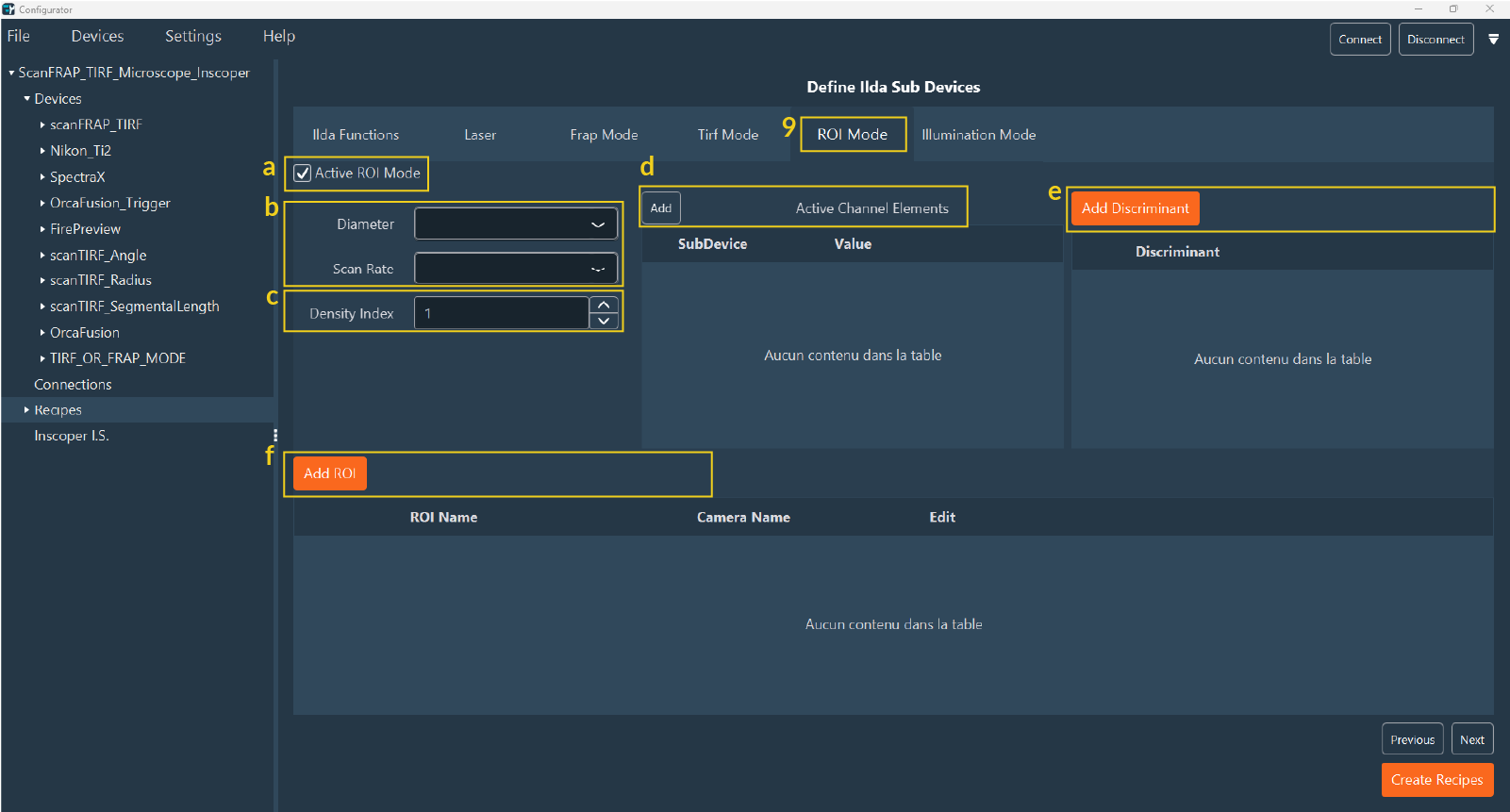
For LightSheet systems, navigate to the ROI Mode tab (9).
- a. Select Active ROI Mode.
- b. Select the sub-devices for density and scan rate.
- c. Specify the Density Index, matching the FRAP diameter set in the Devices tab.
- d. Enable the active channel elements to activate ROI mode for that channel.
- e. Add discriminants.
- f. Add the ROI.
-
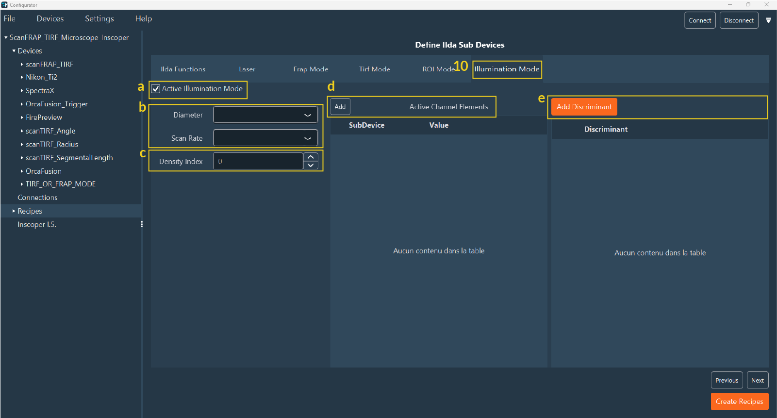
Use the Illumination Mode tab (10) to add a virtual device for selecting illumination modes in multimodal systems (e.g., FRAP, TIRF, Spinning Disk):
- a. Select Active Illumination Mode.
- b. Select the sub-devices for density and scan rate.
- c. Specify the Density Index (this must match the FRAP diameter in the Devices tab).
- d/e. Add active channel elements and discriminants.
-
Click on Next to proceed to the last step, the FLIM tab (11) for systems equipped with a FLIM module:
- a. Add all devices responsible for the Delay.
- b. Add discriminants.
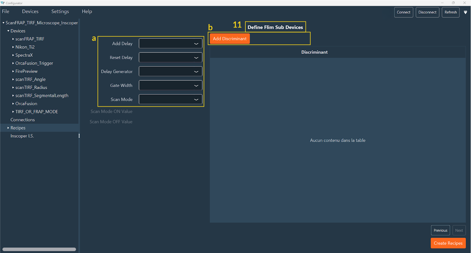
-
Click Create Recipes to finalize the configuration.
Next Step: Your recipes are now created. You can finalize the Inscoper Imaging Software (IIS) Configuration to complete the setup.