ILDA functions for FRAP, TIRF, FLIM modules
- If you have an additional module such as a FRAP, TIRF or FLIM module, ILDA fuctions will need to be configured. You can continue setting up the recipe by clicking Next.
-
In the Ilda Functions tab, select your device connected
to the Ilda connector (only available for the XL box type).


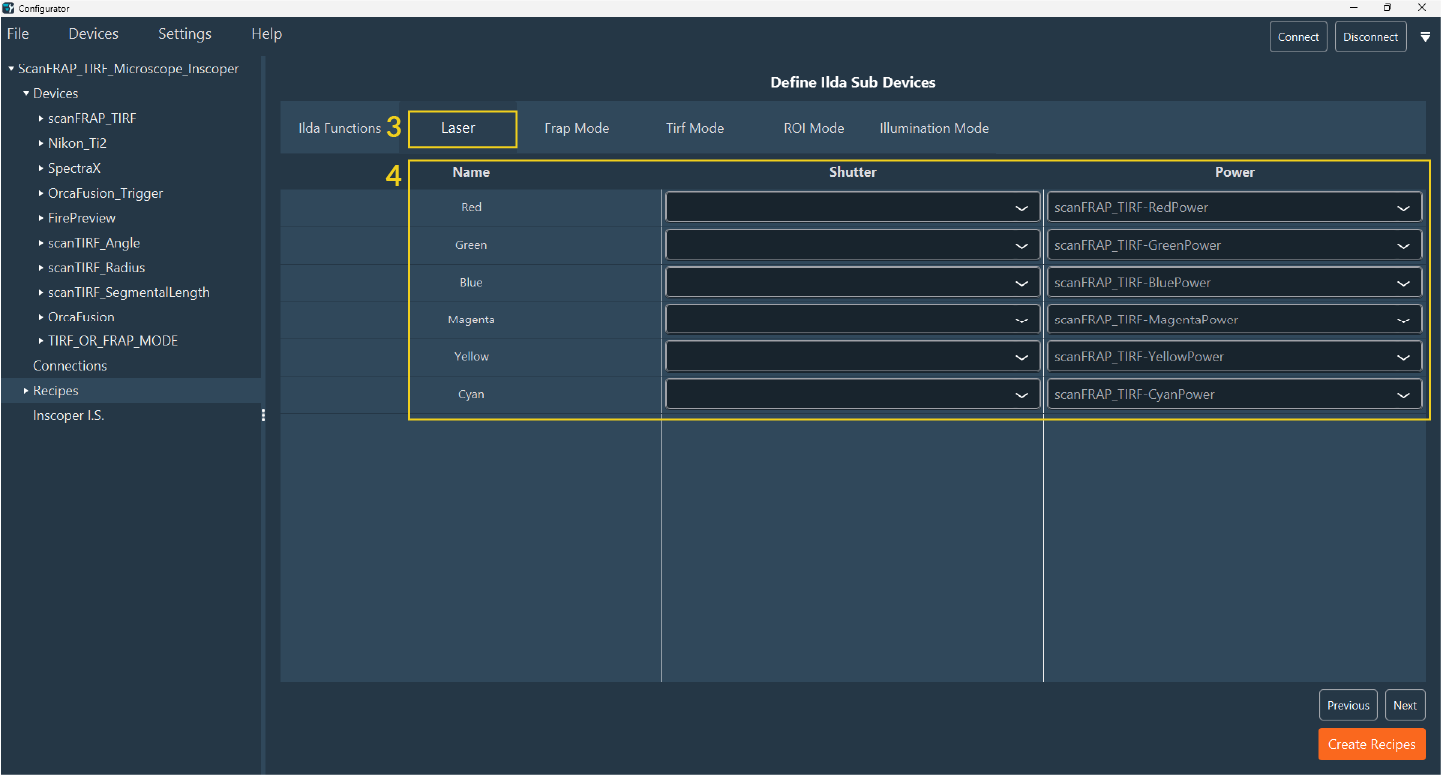
- All Ilda functions and all parameters in each function are automatically loaded. Check if all functions and parameters are correct, then click on the Laser tab.
-
In the Laser tab, you will find a table where you must specify the shutter and
power Sub Devices for each laser line. Select the Sub Devices by clicking on the
drop-down menu in each column.
- Then click on the FRAP Mode tab.
-
Select Active Frap Mode to access this option in the
interface (if the box is unchecked, no FRAP parameters appear in the
interface):
-
Add camera calibration.
Note:If you have several cameras indicate if you want to use the same calibration for all cameras or a different one. If you want to use the same calibration indicate the same number in the calibration column for all cameras

-
Add camera calibration.
- When it’s done, then go to the TIRF Mode tab.
-
Select Active TIRF Mode to access this option in the
interface (if the box is unchecked, no TIRF parameters appear in the interface):
-
Add discriminant for the TIRF calibration like Objective, filter cube,
lasers.

-
Add discriminant for the TIRF calibration like Objective, filter cube,
lasers.
-
If you have a lightsheet system, go to the ROI Mode tab (for ROI
scanning).
-
Add ROI.

-
Add ROI.
-
The Illumination Mode is used to add a virtual device to
select the illumination mode (e.g. if you have a multimodal system with FRAP,
TIRF, Spinning Disk).
- Select Active Illumination Mode to access to this option in the interface.
- As with FRAP, select the Sub Device that determines the density and the scanRate.
- Specify the density index which must to be the same number than in the Sub Device frap diameter in the Device tab.
- Add active channel elements.
- Add discriminant.

-
Click on Next to proceed to the last step, which is the
FLIM configuration.
Fastpath:If you don’t have the FLIM module, you can directly click on Create Recipes.
- Add all devices responsible for the Delay.
- Add discriminant.

- Click on Create Recipes. Your recipe is created. You can now finalize your I.S. configuration.