Tiling
Creating a Tiling
Use the Tiling dimension to capture large sample areas through automated mosaic acquisition.

Switch to Positions
You can toggle directly to the Positions dimension using the Switch to Positions button if you require discrete capture points instead of a continuous mosaic.
- Generate a low-resolution Preview of the sample.
- Move the stage to the region of interest and focus the image.
- Click Add tiling to append a new tiling configuration block to the dimension list.
- To configure the parameters of a tiling block, click the Pen icon. To delete a block, click the Red Cross.
- Assign a label to each tiling block by modifying its field in the Tag column.
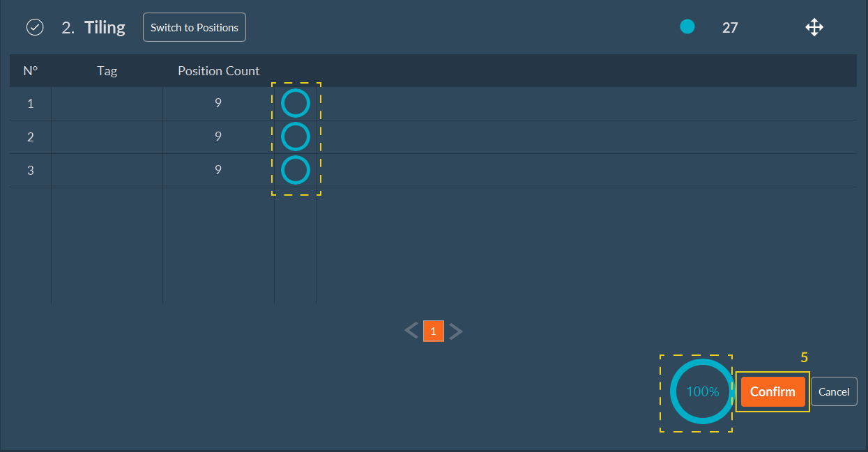
- Click Confirm to save the tiling configuration.
Setting Up a Tiling Layout
Define the physical tiling boundary using two topological methods:

-
Define Boundaries:
-
By Edge: Click Add to drop coordinates outlining the region of interest. The software connects these points to form a polygon.
- Clear the bounding box using Remove All, or delete a single vertex by right-clicking it.

-
By Center: Drive the stage to the center of the acquisition region and click Set. Then, select either a rectangular or circular tiling geometry.
- For a rectangle, specify the bounding grid dimensions (e.g., 3x3 tiles). For a circle, specify the bounding diameter.

Note
Use the right-hand panel controls to manually jog the hardware stage and manage your defined coordinate vertices.
-
-
Define Tile Overlap: Set the overlap percentage between adjacent frames. A 10% overlap is standard for downstream stitching.
- Enable Auto Mode to let the software calculate the overlap ratio based on your specified coordinate boundaries.
- To manually dictate the translation distance between individual tiles, enable the Custom Step option via the Display Settings menu.
Important
Accurate overlap is necessary for successful post-acquisition image stitching.
-
Select Read Mode: Choose the scanning path (e.g., Spiral, Snake) the stage executes during acquisition.

-
Generate a Focus Map: To compensate for uneven sample topology across a tiling area, create a Focus Map. Navigate the XY plane using the interface joystick or by clicking within the tiling map. Adjust the Z-focus at various locations, and click Add to store each point.
- Add points as necessary to model the sample's topography. Right-click any point (orange indicator) to remove it.
- The software applies a color gradient overlay to the map, representing the interpolated Z-surface altitude across the acquisition region.

-
Configure Z-Stack Integration:
- Select the corresponding checkbox inside the tiling editor to center Z-Stacks around the interpolated Z-values stored in the Focus Map.
- If unchecked, the sequence uses either global Z-Stack parameters or the current live Z-position.
-
Click Confirm to save the spatial tiling configuration.
Note
- Orange squares: Indicate saved boundary vertices or focus map reference anchors.
- Purple square: Indicates the real-time physical position of the XY stage.
Tip
Use the GoTo button to rapidly drive the mechanical stage back to a previously saved topological reference position.
Focus map automated setup for simple and multiple tilings
The Automated Focus Map is an optional software feature of the Inscoper I.S. that automatically generates a relief map of the biological sample when performing tiling imaging.

- Click Focus Map Start within the Tiling dimension to begin configuration.
-
Set the following parameters for both simple and multiple tilings:
- a. Select the step and size of the Z-stack.
- b. Select an existing pattern.
- c. Select the channel used to acquire the stack.
- d. (Optional) Select Filter unsure position and configure the corresponding parameters:
- i. Filter Radius: Smooth noise by replacing each pixel with the median of its neighbors (e.g., 0 = no smoothing, 1 = median of a 3x3 square surrounding the pixel, 2 = median of a 5x5 square surrounding the pixel).
- ii. Background ROI: Select the Region of Interest (ROI) used to automatically calculate background values.
- iii. Background: Define the mean background value.
- iv. Background Delta: Define the acceptable noise amplitude.
- v. Valid Pixels: Define the minimum percentage required to validate a position.
-
Select the tiling region for which to create the Focus Map.
-
Click Start. The system scans all points, generates the Focus Map, and displays the determined focal points. A progress bar indicates the current progression per tiling region. Once the Focus Map is complete, the software redirects you to the Tiling dimension interface.

-
Click Confirm to validate and proceed with the acquisition sequence setup.