Configuration
Use the Configuration tab to control each motorized device on the microscope, find the correct focus plane, select the optimal camera settings, and set up the channels.
Overview
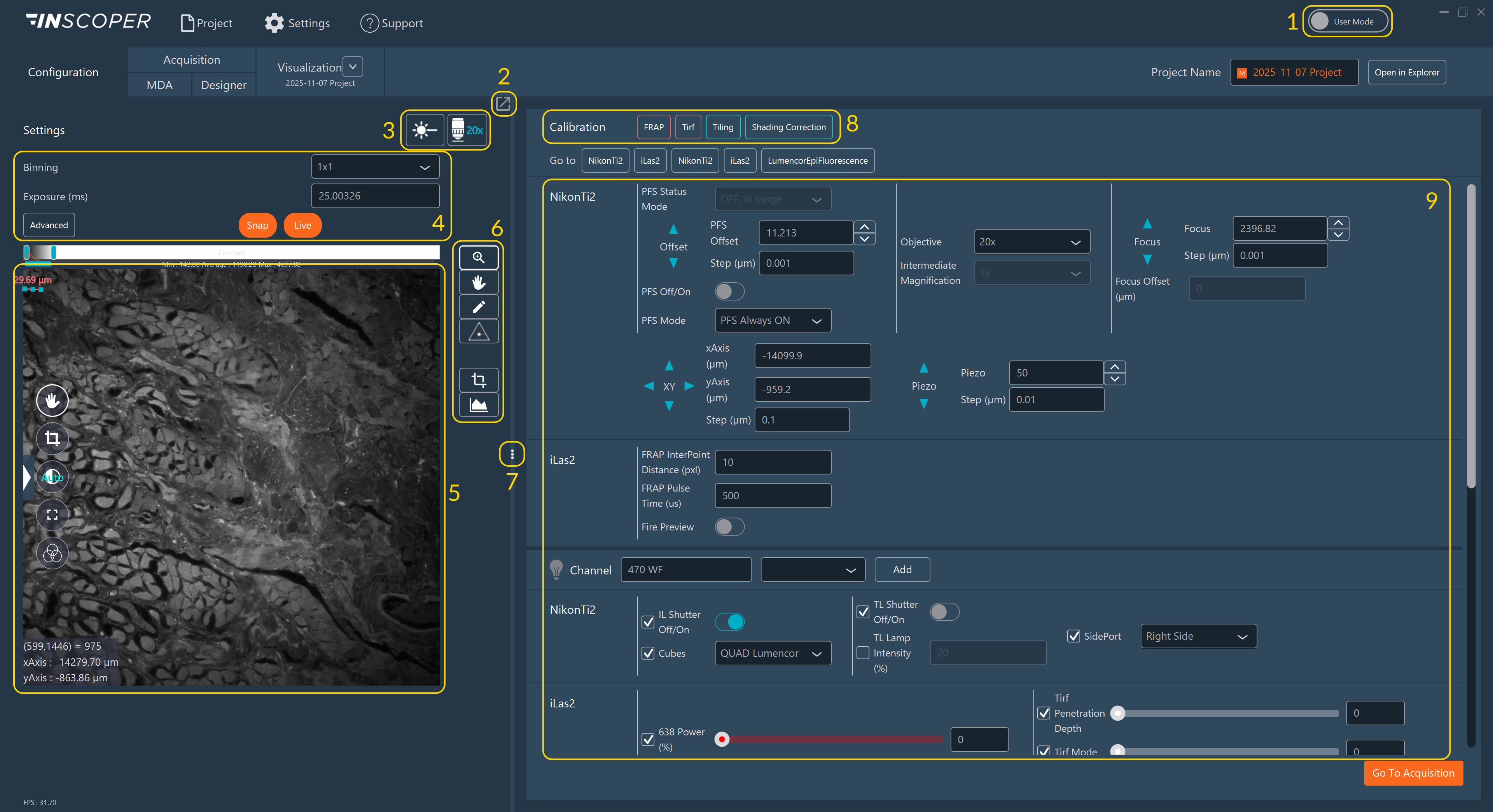
The configuration interface is divided into several sections:
-
User Modes: Two access levels are available in Inscoper I.S., based on the user's level of expertise in microscopy:
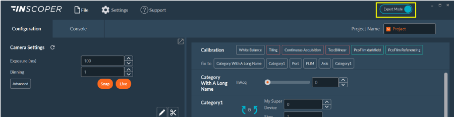
Mode Description 
Expert Mode provides unrestricted access to all system settings and parameters. This mode is intended for microscope facility managers and researchers experienced in microscopy. 
User Mode provides restricted access to selected settings and parameters. The restrictions are fully customizable, ranging from basic channel configuration to the most advanced camera and device settings. This mode is intended for biologists who are not yet experienced with microscopy. Note
Users can switch from User Mode to Expert Mode at any time. Facility managers can set a password to restrict access to Expert Mode.
-
Split Screen: For dual monitors, detach the live camera feed view to a separate screen to decouple it from the settings panel.
- Channel/Objective Access: Switch between defined channels and objectives with a single click.
- Camera Settings: Configure camera parameters.
- Live Viewing: View the real-time image feed.
- Image Tools: Interact with the image display.
- Divider: Adjust the screen size of the central camera view and the side settings panel.
- Calibration Protocols: Access optical and stage calibration tools (see Tiling Alignment and Shading Correction).
- Motorized Devices: Access connected motorized hardware, create new channels, and save them to the project.
Rename the current project using the text field in the top-right corner.
Camera Settings
The software supports up to 4 cameras simultaneously. Create and save parameter presets for each camera using this section.
.svg)
- Select a camera preset from the drop-down list.
-
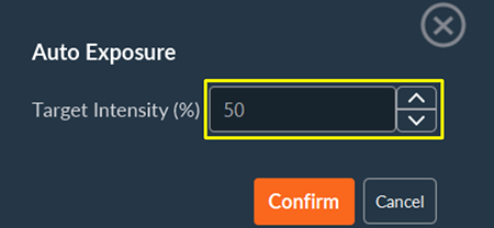
Adjust the exposure time and pixel binning. If Auto Exposure is enabled in the Display Settings, an Auto button is available. Auto Exposure adjusts the exposure time to prevent pixel saturation by analyzing the real-time pixel histogram.
-
Access advanced camera settings to create custom presets:
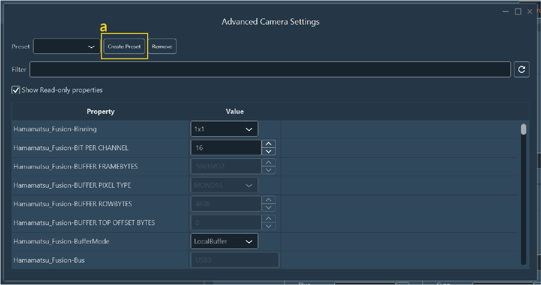
-
Click Create Preset:
-
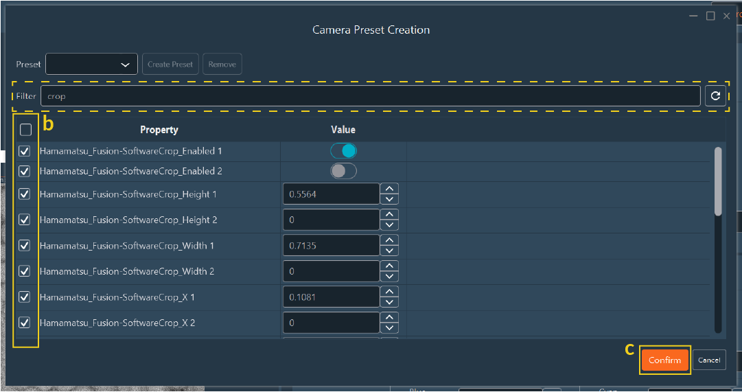
Select the parameters to include in the new preset using the checkboxes. Use the search bar to filter the parameter list.
- Click Confirm, then assign a name and save location for the preset.
-
Live Image Interaction
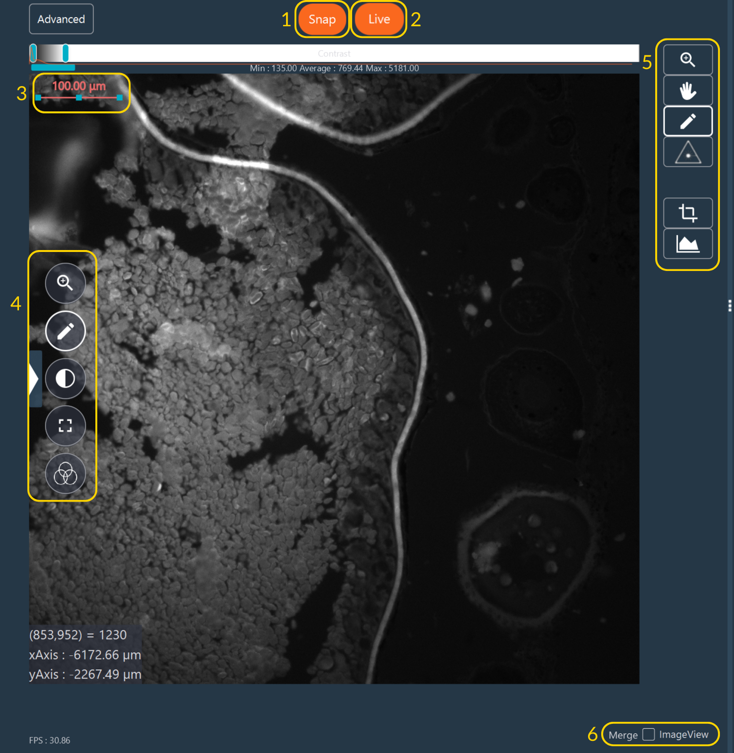
Use the toolbars to interact with the live image stream:
- Snap: Capture a single image frame.
- Live: Toggle the real-time camera stream.
- Scale Bar: Double-click to modify orientation and physical length.
-
Tools to interact with the image:
Tool Description 
Toggle automatic or manual contrast adjustments. Use the intensity sliders above the camera view to establish manual contrast boundaries. 
Toggle full-screen mode. Exit by pressing the button again or clicking the 'X'. 
Apply LookUp Tables (LUTs) to the image display in real time. Options include no LUT, single-color LUT, or a preset LUT. LookUp Tables (LUTs)
Applying a LookUp Table maps raw grayscale intensity values to a specific colored gradient. This is critical for drawing ROIs accurately during quantitative assays, as pseudo-colored "heatmaps" (like the fire LUT) visually exaggerate subtle intensity differences that remain indistinguishable to the human eye in standard grayscale.
Available preset LUTs include:
- Pixel indicator: Highlights saturated (overloaded) pixels in red.
- Inscoper ratiometric: Designed for visualizing ratiometric images.
- Multicolor LUTs: Standard palettes such as "fire", "physics", etc.
-
Advanced Image Tools (a secondary toolbar with specialized functions):
Tool Description 
Pan across the field of view by dragging and dropping. Scroll the mouse wheel to move along the Z-axis. 
Zoom digitally by scrolling the mouse wheel over the image. 
Draw Regions of Interest (ROIs) or crop the live image. Configure as a hardware sensor crop or software crop. 
Create and manipulate ROIs to precisely control processing, cropping, and photo-manipulation.
Creation Modes
Tool Mode Description 
Pen Add one or multiple discrete ROIs to the view. 
Scissors Remove a drawn sub-shape from an existing ROI, retaining the external boundary. Drawing Geometries
Select the desired geometry tool to draw the ROI boundaries:
Tool Shape Description 
Line Draw a 1D straight line. 
Curve Draw a 1D freehand line. 
Rectangle Edge Draw the 2D perimeter of a rectangle. 
Filled Rectangle Draw a solid 2D rectangular area. 
Circle Edge Draw the 2D perimeter of a circle. 
Filled Circle Draw a solid 2D circular area. 
Free Form Edge Draw a custom closed 2D perimeter. 
Filled Free Form Draw a solid, custom closed 2D area. ROI Management
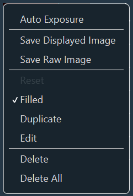
Right-click an existing ROI on the image canvas to access the spatial management window:
- Fill internal areas.
- Duplicate existing ROIs.
- Edit ROI: Manually define precise micron dimensions and specify absolute center coordinates within the camera field of view.
- Remove single or all drawn ROIs.
Tool Plugin Description 
Fire on Click Trigger targeted photo-manipulation lasers. (Requires the FRAP module to be installed). 
Crop Access Configure either hardware (sensor-level) or software (digital) cropping. Draw a ROI, select the target mode, and click Confirm Crop. 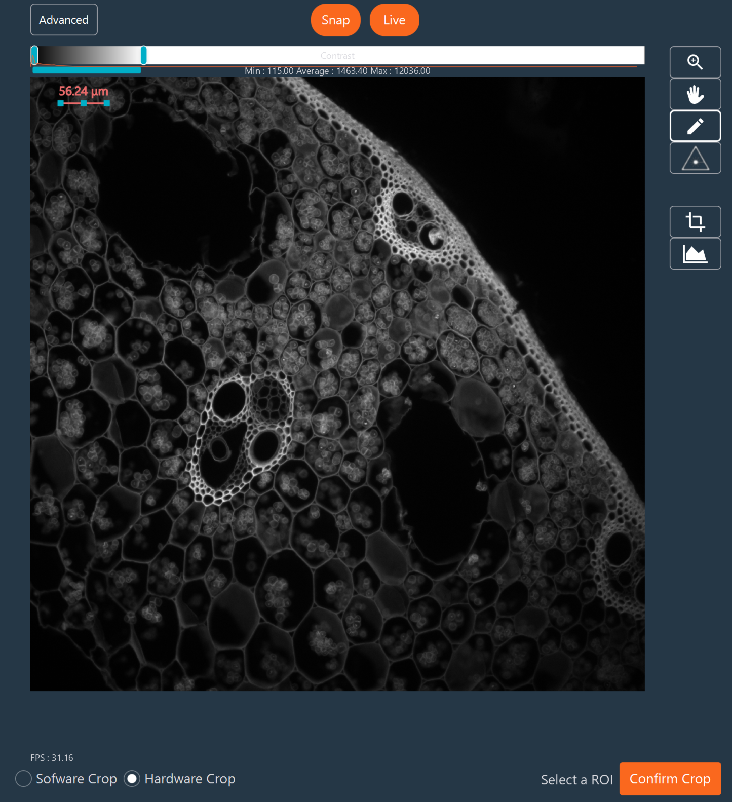

Histogram Access Dock the quantitative histogram (or other 1D visualizations) below or to the right of the image panel. Adjust the X-axis scaling relative to camera bit-depth by hovering over the top of the histogram. 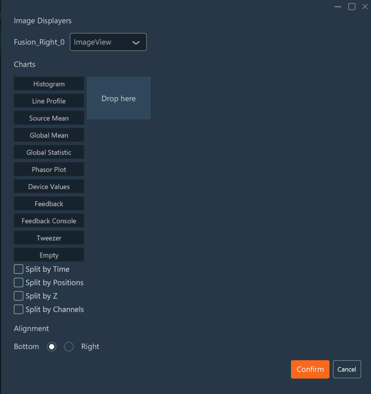
-
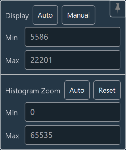
Contrast Adjustment: Hover over the contrast bar located at the top of the image view. Use the high/low threshold sliders to modify the minimum and maximum displayed values, effectively redefining the black and white points to optimize the visual dynamic range. Zoom directly within this micro-histogram tool.
-
Merged Images: If the system is equipped with multiple cameras, use the Merged images toggle to display a combined live multiplexed superposition of all active camera streams.
Motorized Device Control
Interacting with Devices
This panel provides control over hardware connected to the Inscoper I.S., including the microscope stand, motorized XY stages, optical shutters, illumination sources, filter wheels, piezo Z-drives, and microfluidics pumps.
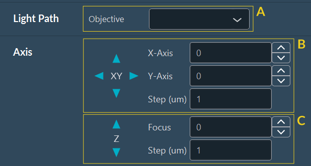
- Use panel (A) to move the objective turret.
- Panels (B) and (C) provide virtual joysticks to move the XY stage and Z-focus. Each arrow moves the stage or focus in the selected direction by the defined step.
Creating and Loading Channels
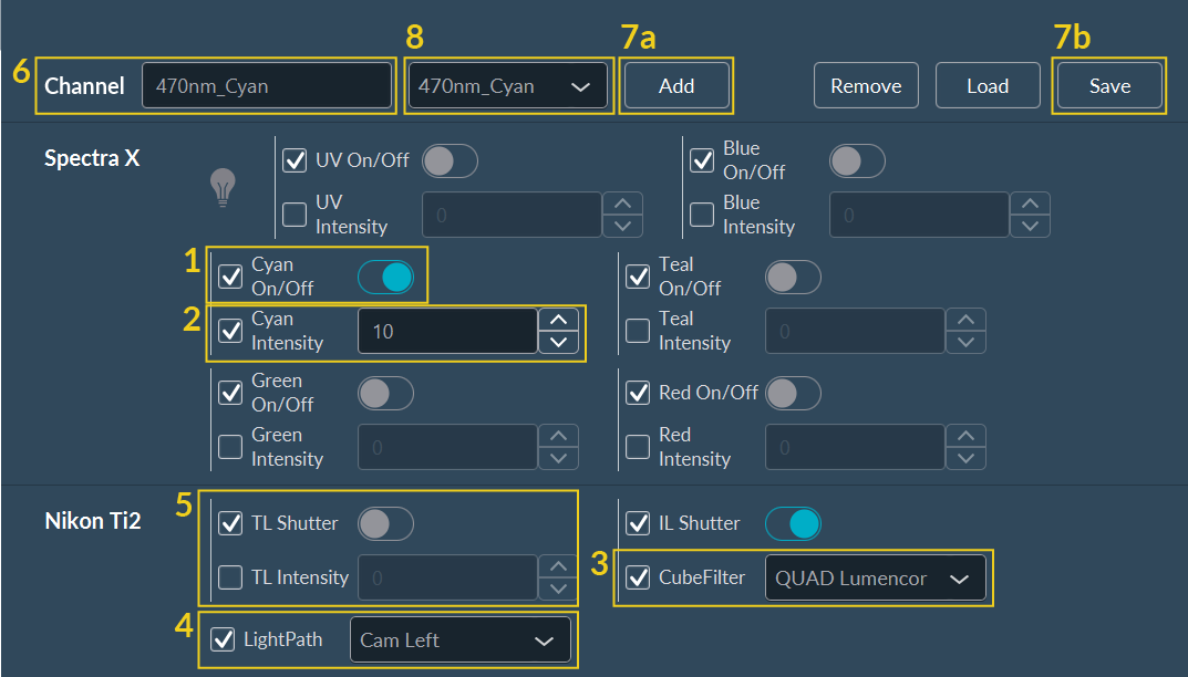
Expert users have direct control over optical path components (filter wheels, dichroic cubes, LEDs, laser lines). To configure a new fluorescent imaging channel:
- Select the excitation light source.
- Set its output intensity.
- Select the optical filter cube.
- Select the LightPath geometry.
- (Optional) Select brightfield LED illumination to use instead of, or simultaneously with, the fluorescence path.
- Assign a name to the channel configuration.
-
Save the channel:
- a. Temporarily (for the current session) by clicking Add (User Mode).
- b. Permanently (to the database) by clicking Save (Expert Mode).
-
The newly created channel populates the channel list.
Camera Port Alignment
Many microscopes use more than one camera port (e.g., left and right ports). It is critical to select the correct active port before initiating imaging. Failing to select the active port may result in blank images or hardware errors during acquisition.
System Calibration
Access critical optical and stage calibration tools required for various sequences.
Tiling Alignment Calibration
Tiling calibration aligns the camera sensor's X/Y orientation with the motorized XY stage axes. This hardware alignment is strictly required for accurate image stitching.
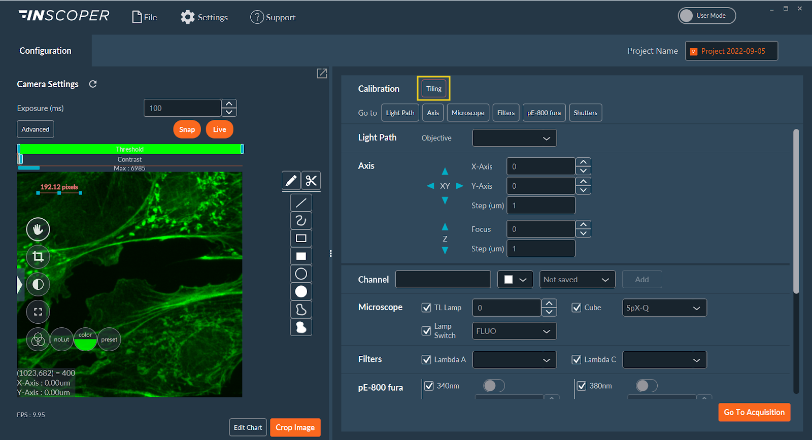
- Click Tiling in the Calibration section. The indicator is orange if uncalibrated, and turns green when calibrated.
-
Select a calibration mode:
Mode Description 
An automated routine. Click Automatic and confirm. 
A manual routine where you verify and correct the orientation.
Streaming Requirement
Stream camera data in Live mode and bring a sample into focus before initiating either calibration.
Manual Calibration Protocol:
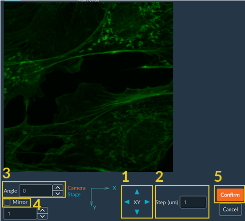
- Move the XY stage using the virtual joystick. Confirm that the stage movement matches the image's orientation on the screen.
- Adjust the movement step size for finer control.
- Apply rotation to the live camera feed until it aligns with the stage movement axes.
- Apply mirroring to the live camera feed until it aligns with the stage movement axes.
- Click Confirm to save the calibration.
Shading Correction Calibration
Shading Correction (flat-field correction) ensures uniform illumination intensity across the camera field of view, compensating for light source vignetting or unevenness. Perform this calibration using a uniform reference sample, such as an auto-fluorescent slide (e.g., Chroma).
Executing the Shading Calibration Sequence

-
Click Shading Correction.

-
Specify the number of acquisitions. The software averages the captured frames to reduce noise.
-
Click Confirm to start the calibration routine.

-
Once the calibration is complete, validate it:
- Verify the result by clicking Test Shading in Live mode.
- View the generated shading image map by clicking Show Shading Image.
-
Click Confirm to save the calibration.
- Once calibrated, the Shading Correction indicator turns green.
Applying Shading Correction via the Data Processor
Once calibrated, shading correction is not applied automatically; it must be explicitly invoked within the data processing pipeline.
- In Expert Mode, construct a data processing pipeline containing the Raw Data, Shading Correction, and Tiling nodes.
- Assign this pipeline to your sequence during the Acquisition setup.
-
Click Edit Parameters on the Shading node.

-
Select the channel(s) that require shading correction.
-
Click Confirm to validate your selection.
