Multiwell Plate Mode
Overview
The Multiwell Plate Mode automates the imaging of standardized microplates. Access this feature from either the Positions or Tiling dimensions by clicking the Set button.

| Button | Description |
|---|---|
 |
Select Wells: Click to highlight the wells you intend to image. |
 |
Auto Move: Once the plate is calibrated, activate this toggle to automatically physically move the XY stage when you select a well. |
 |
Unselected: The well is excluded from the acquisition. |
 |
Selected: The well is included in the acquisition. |
 |
Current Position: Indicates the real-time position of the objective relative to the plate. |
Calibration
You must calibrate the system to map the software's virtual coordinates to the physical dimensions of the specific well plate, optimizing precise XY stage movement.
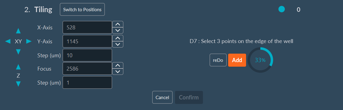
- Click Find Center to initiate the semi-automated calibration protocol.
- Select a well on the virtual map to serve as the calibration reference.
- Manually drive the mechanical stage to this physical well, if not already positioned there.
- While viewing the live image, move the XY stage to align the virtual crosshair precisely with the physical edge of the well, then click Add.
- Repeat this alignment process two more times on different sides (e.g., top, bottom, left) of the same well to establish the geometry.
- Click Confirm to complete the calibration.
Once calibration is complete, the software reliably and automatically navigates to any well on the plate.
Multiwell Mode in the Positions Dimension
Use this mode to capture distinct, single-field-of-view images within designated wells.
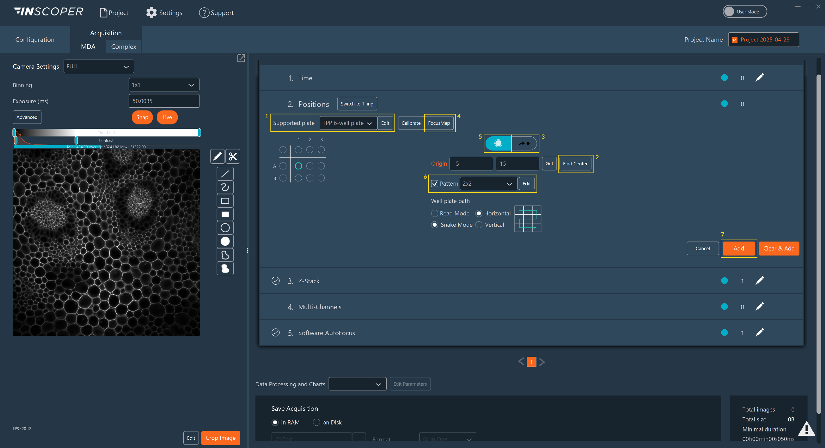
- Select the plate format (e.g., 96-well, 384-well) from the Supported plate dropdown list.
- Calibrate the well plate using the Find Center tool.
- You can now automatically move the stage directly to specific wells.
- Create a Focus Map for the desired wells, if necessary (crucial for maintaining focus across uneven plate bottoms).
- Select the wells to image on the virtual map.
- To generate an automated imaging pattern within each well, check the Pattern box. Specify the number of desired capture points and the minimum Euclidean distance between them.
- Click Add to confirm the settings and populate the position list.
Tip
Fast Selection: In the virtual well plate map, click a row letter or column number to select the entire row or column. You can also click the top-left corner to select the entire plate. To select multiple discontinuous wells, click and drag your mouse to create a selection box.
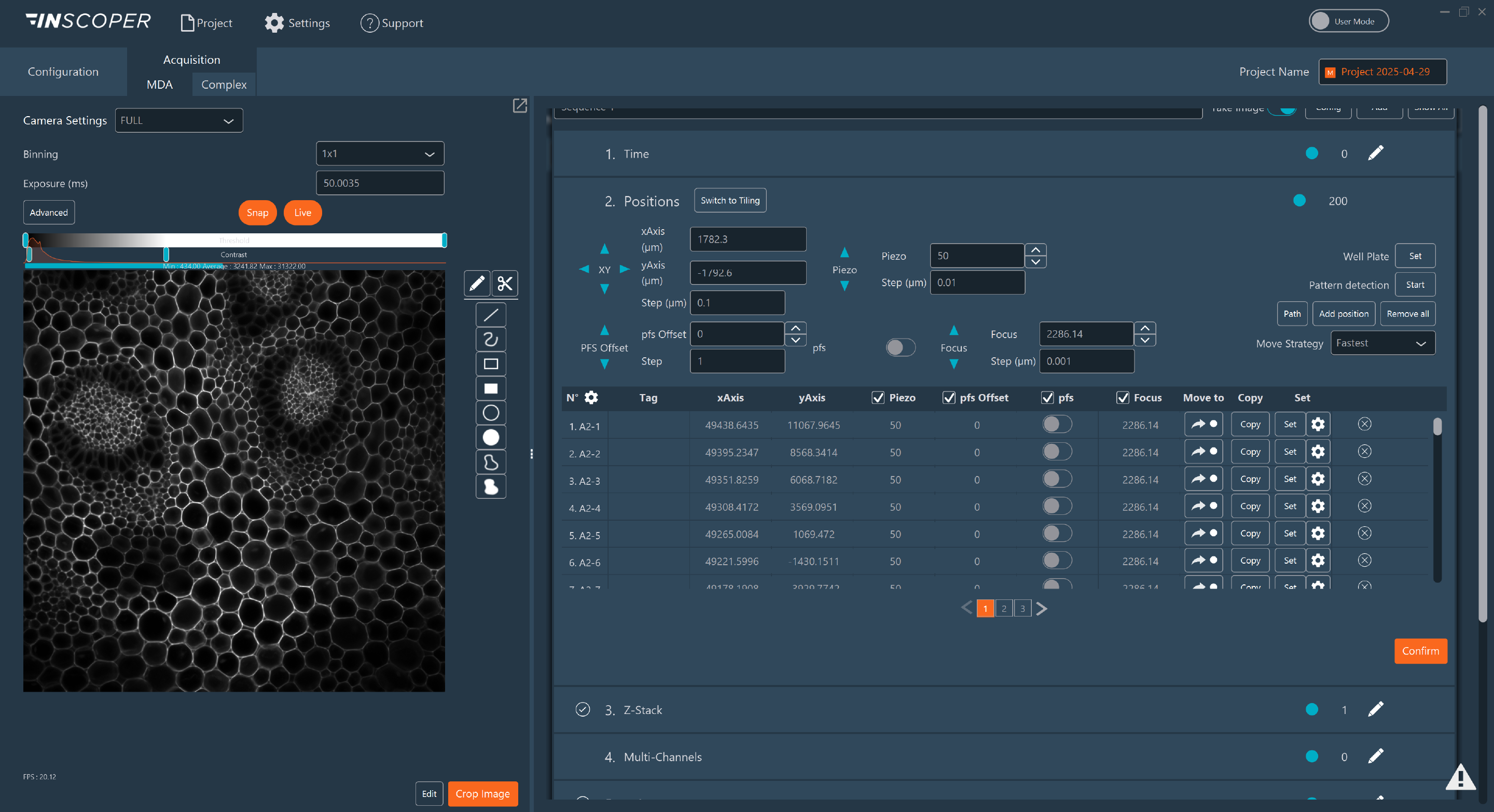
All generated coordinates are added to the Positions dimension list.
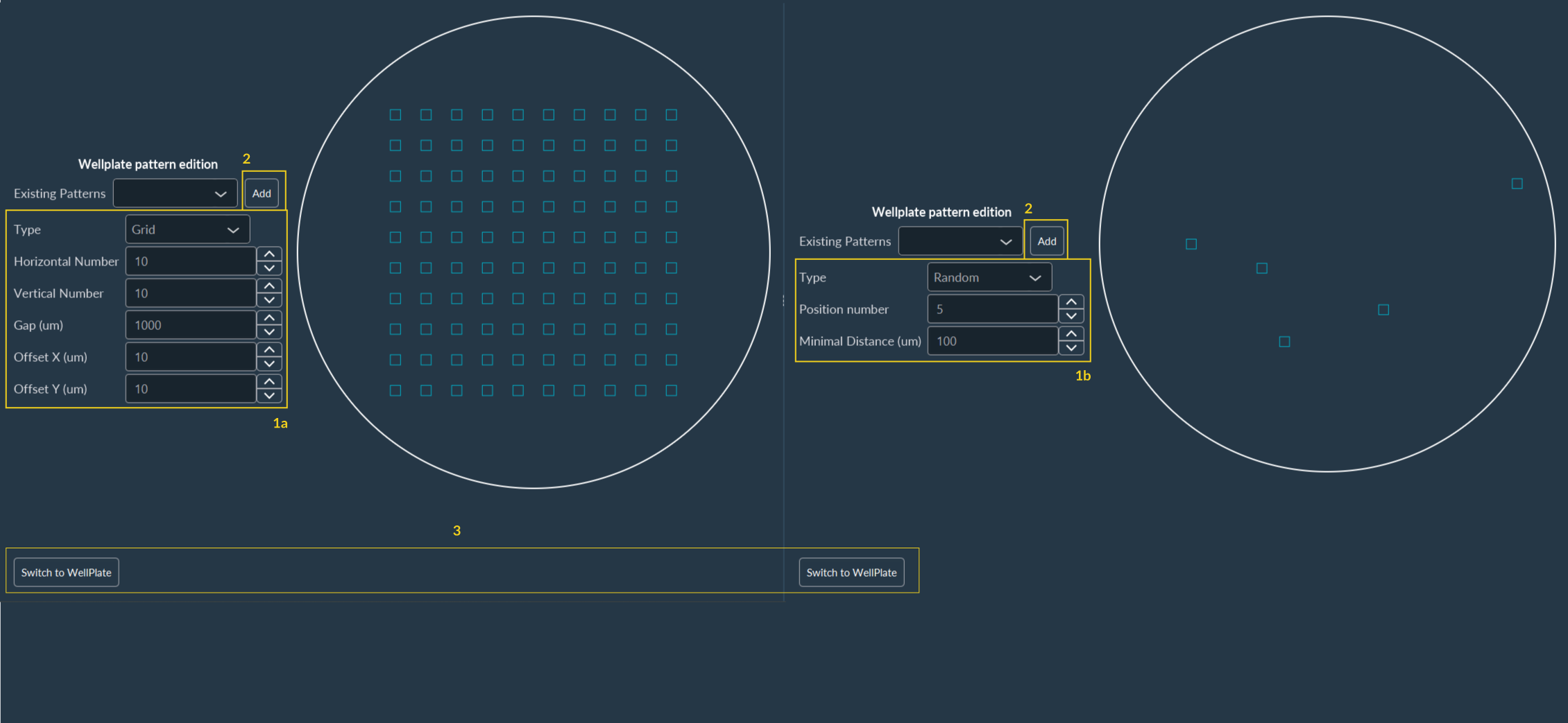
Editing a Pattern
Click Edit next to a pattern to modify its distribution parameters:
- Select the pattern strategy: Grid or Random.
- For a Grid, specify the number of horizontal and vertical images, the spacing distance between adjacent positions, and the X/Y offset (to translate the entire grid relative to the well center).
- For a Random pattern, specify the total number of positions and the minimum required exclusion distance between them to prevent overlap.
- Click Add to update the pattern.
- Click Switch to WellPlate to return to the interactive plate overview.
Multiwell Mode in the Tiling Dimension
Use this mode to acquire large, stitched mosaic images covering entire wells or significant portions of them.
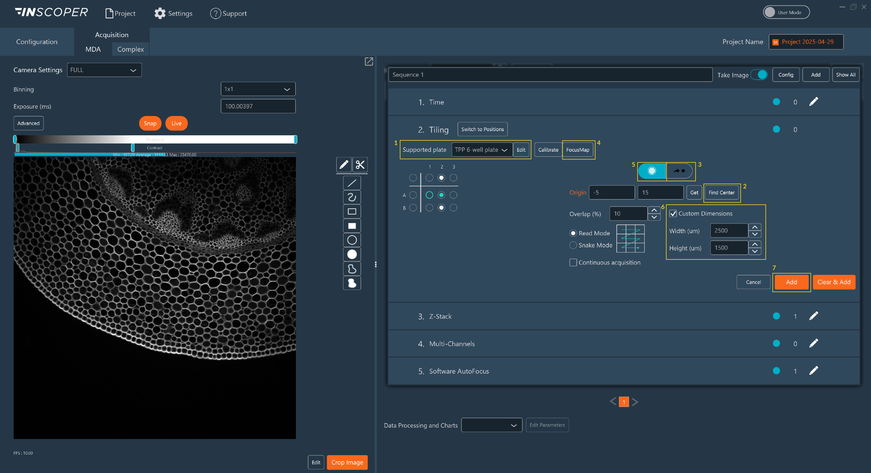
- Select your plate format from the Supported plate dropdown list.
- Calibrate the well plate using the Find Center tool.
- You can now automatically move the stage exactly to specific wells.
- Create a Focus Map for the desired wells, if necessary.
- Select the wells you intend to image on the virtual map.
- Check the Custom Dimensions box to configure the specific tiling size, tile overlap percentage, and scanning read mode to be applied uniformly within each selected well.
- Click Add to confirm your settings and generate the tiling matrices.
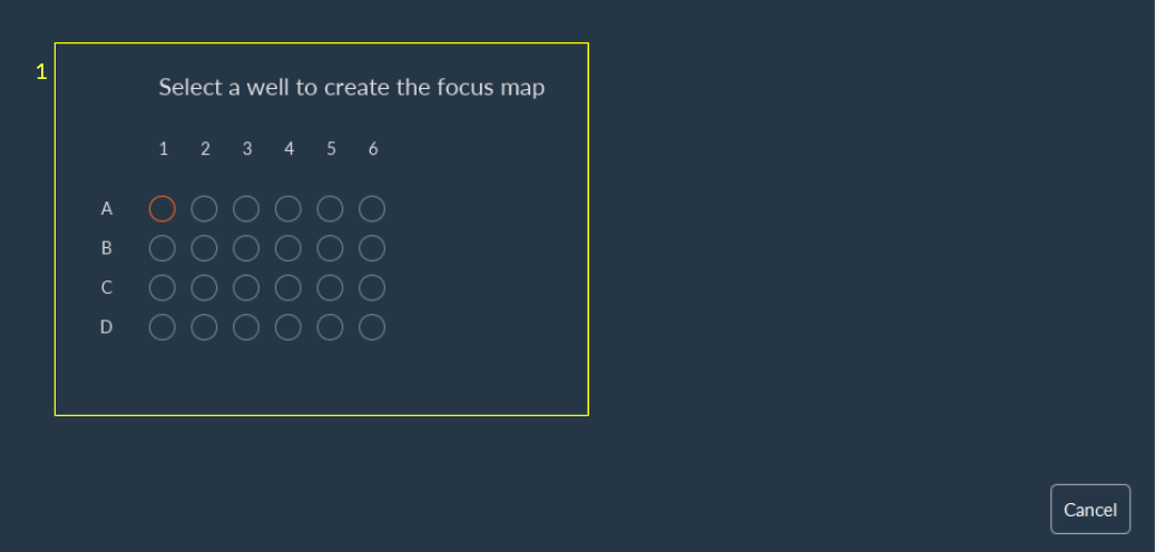
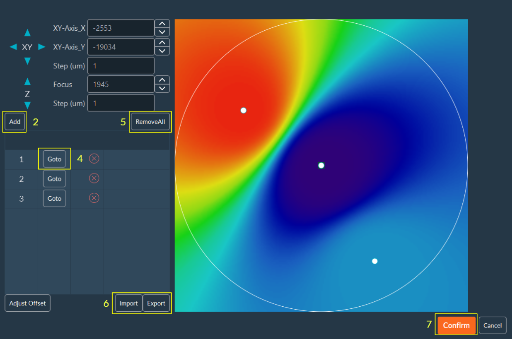
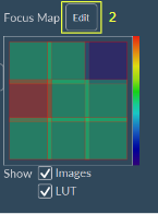
Manual Focus Map Setup
A Focus Map creates a topological Z-surface to compensate for sample drift or uneven plate substrates.
-
Select the specific well for which you want to create a Focus Map.
-
Move the stage to a desired topological anchor point within the well, manually adjust the focus until sharp, and click Add.
- Repeat this process at multiple disparate points until the Focus Map adequately covers the imaging area. The software interpolates the focus between these points.
- Click Go to to move the stage back to a previously saved focus anchor point for verification.
- Click Remove all to clear all points from the current map.
- You can also import or export a saved Focus Map using the respective buttons (useful for standardized, recurring assays).
-
Click Confirm to lock in your Focus Map.
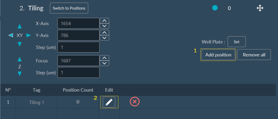
Automated Focus Map Setup
The Automated Focus Map is a software feature of the Inscoper I.S. that automatically generates a hardware-driven relief map of the biological sample before executing tiling imaging.
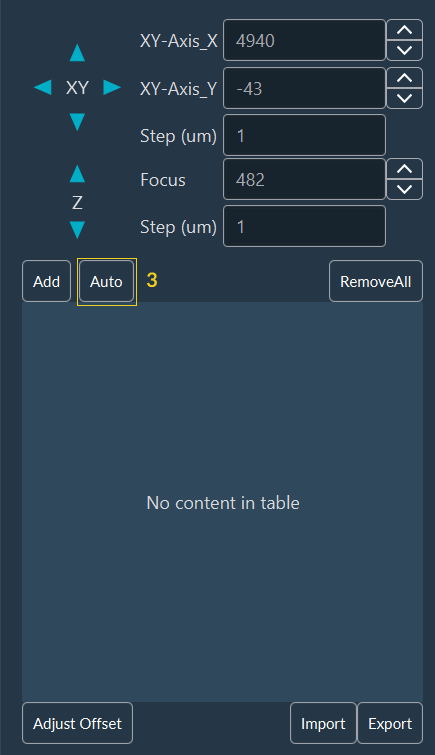
- In the Tiling dimension, click Add position to configure the tiling matrix.
-
Click Edit to customize the tiling parameters and adjust the Focus Map.
-
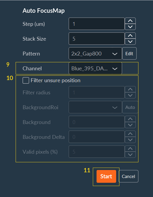
Click Auto to configure the automated Focus Map generation.
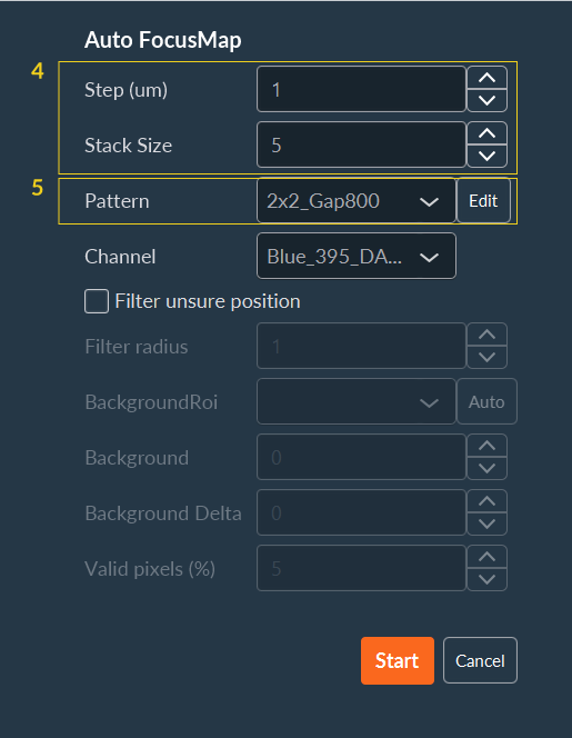
-
Define the step interval and size for the Z-stack.
-
Select an existing sampling pattern from the dropdown list (and proceed to step 9), or click Edit to define a new spatial pattern.
-
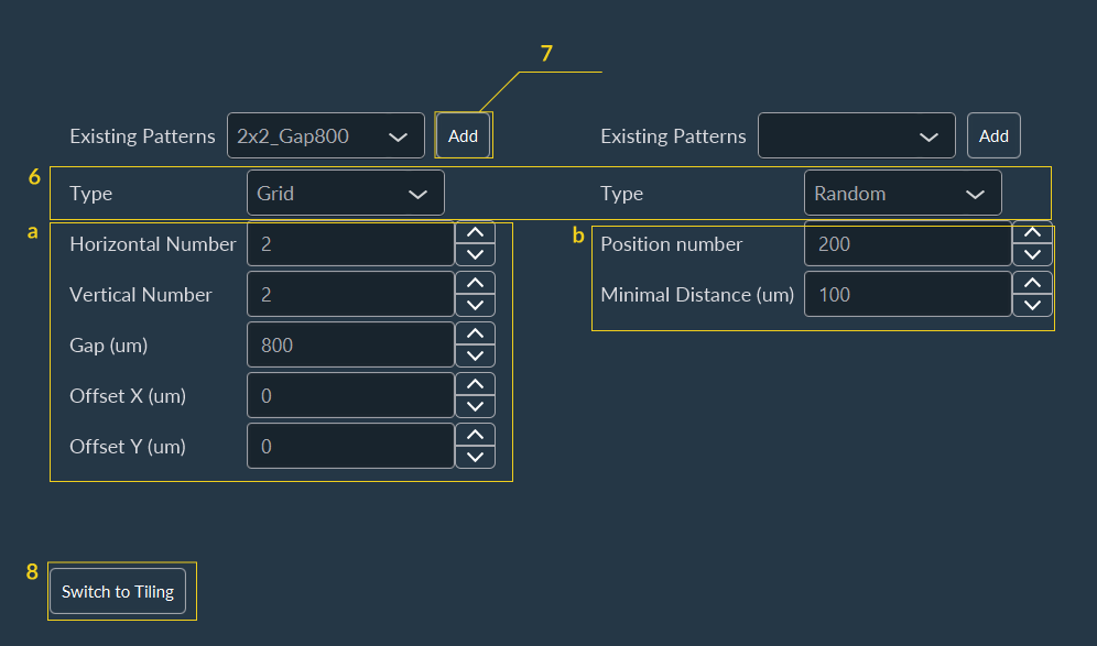
If creating a new pattern, select either a Grid or Random geometric distribution:
- Grid: Specify the total number of images to acquire horizontally and vertically, along with the gap distance between adjacent image boundaries. The X and Y offset values translate the entire pattern grid across the well.
- Random: Specify the total number of positions and the minimum required exclusion distance between coordinate points.
- Click Add to save the distribution pattern.
-
Click Switch to Tiling to return to the primary dimension configuration.
-
Select the channel designated for acquiring the Z-stack during the Focus Map generation.
- To mathematically reject optical artifacts or empty fields, select the Filter unsure position checkbox and configure the rejection parameters:
- Filter Radius: Applies a spatial median filter to reduce high-frequency noise before evaluation (e.g., 0 = no smoothing; 1 = median based on a 3x3 pixel kernel; 2 = median based on a 5x5 pixel kernel).
- Background ROI: Automatically calculates absolute Background and Background Delta values by evaluating a user-drawn Region of Interest (ROI). The Background equals the mean pixel intensity of the ROI, and the Background Delta equals two times the standard deviation.
- Background: Specifies a static mean background intensity value.
- Background Delta: Specifies the permitted noise amplitude threshold.
- Valid Pixels: Sets the required percentage of pixels whose intensity must exceed the background threshold to validate the coordinate position.
-
Click Start to initiate system generation.
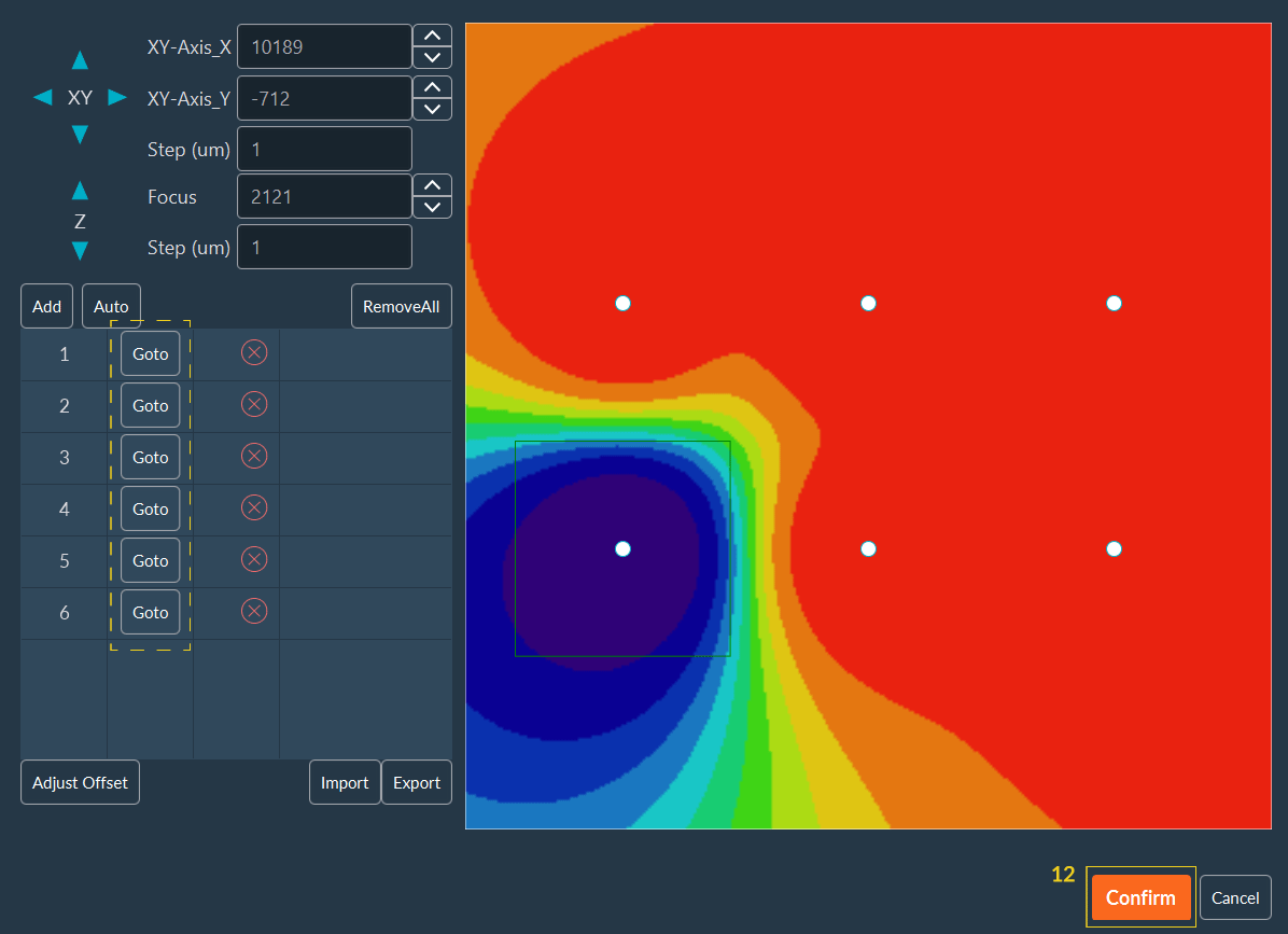
The system navigates to all defined coordinates to create the Focus Map and displays a list of validated anchor points. Click GoTo adjacent to the coordinate or click directly on the thumbnail projection to verify physical focus at any anchor point.
-
Click Confirm to finalize the generated Focus Map.
-
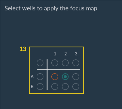
Select the wells to apply the Focus Map to, then click Confirm.
-
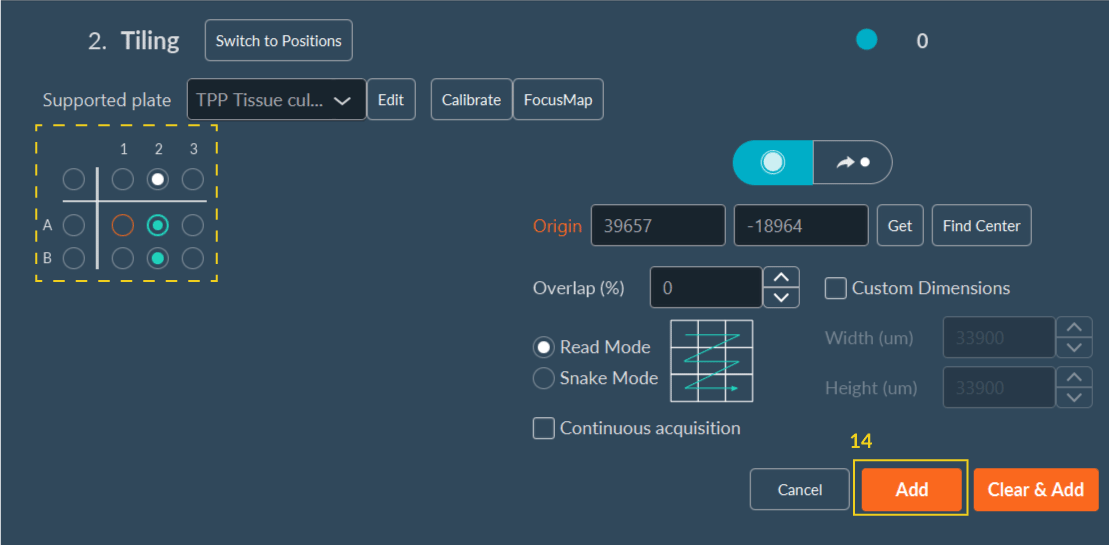
Select the wells to acquire, then click Add.
-
Select whether to use the current Z-position to adjust the Focus Map.
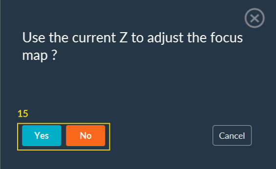
After this step, you can continue configuring your acquisition sequence.