Acquisition Designer
The Designer module is a graphical workspace for building custom acquisition protocols. Combine logical and hardware blocks into an interactive flowchart to define a tailored, multi-dimensional workflow.
How to Access the Designer
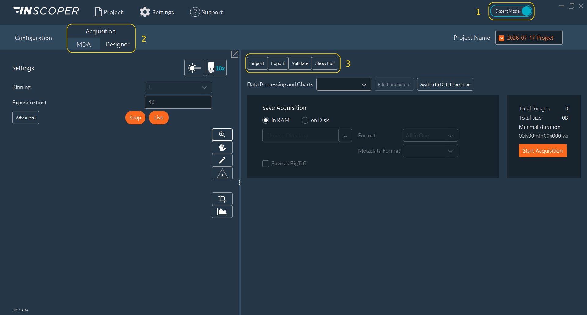
Enable Expert Mode (1), open the main Acquisition tab, then select the Designer sub-tab (2).
Note
Validate and Show Full are only available in Expert Mode (1). In User Mode, the action bar (3) is reduced to Import and Export.
The action bar (3) at the top right of the tab provides four commands:
-
Import: load an existing protocol from a JSON file. The file browser opens in the
complexProtocolsdirectory. A confirmation pop-up appears once the protocol is loaded. -
Export: save the current protocol as a JSON file, by default in the same
complexProtocolsdirectory. -
Validate: register the protocol modifications and recompute the total number of images.
-
Show Full: open the complete graphical workspace used to build the flowchart.
How to Create a Protocol
Click Show Full to open the workspace. The workspace opens as a separate maximized window, on the secondary screen when one is available. Assemble the protocol from blocks placed and linked on the canvas.
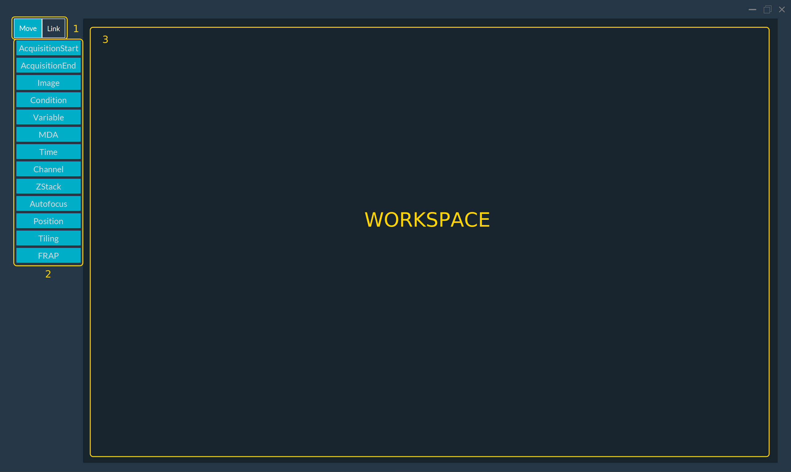
The window is organized in three areas: the tool selector (1), which switches between Move and Link; the block palette (2), which lists every block type available; and the canvas (3), which holds the flowchart.
How to Interact with Blocks
-
Add a block: drag a block from the palette (2) onto the canvas (3) and release the mouse button at the target location.
-
Move a block: activate the Move tool (1), then drag the block across the canvas.
-
Connect two blocks: select the Link tool (1), click the source block, then click the target block. The Designer draws a directional flow arrow between them.
-
Configure a block: switch back to Move mode (1), then double-click the block to edit its parameters.
List of Available Blocks
-
AcquisitionStart: mandatory marker defining the protocol start point.
-
AcquisitionEnd: mandatory marker defining the protocol end point.
-
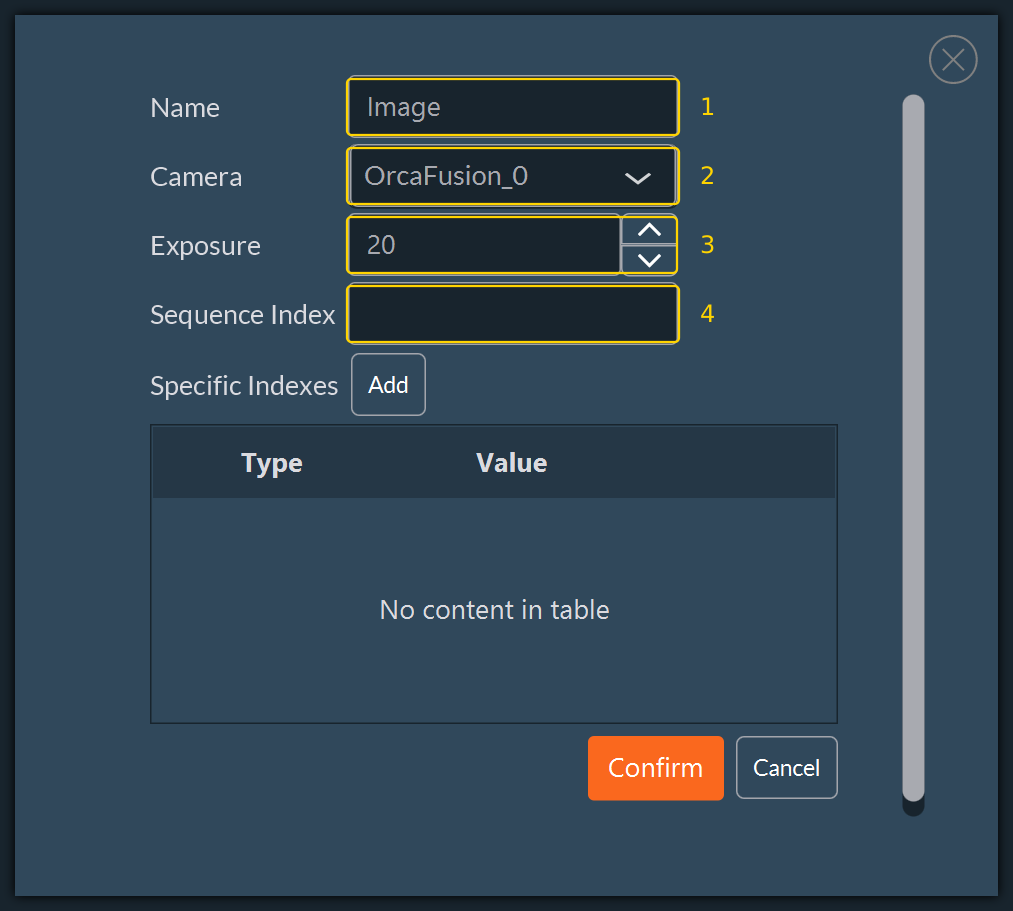
Image: captures raw data. Set the block Name (1), the Camera (2), the Exposure time in milliseconds (3), and the Sequence Index (4).
-
Condition: evaluates a logical expression and splits the flow into two branches.

Four parameters are available: Name (1), If True Text (2), If False Text (3), and Condition (4). The two text fields (2) and (3) set the labels drawn on the outgoing branches; they default to
YesandNoand may be renamed.-
No (loop back): if the expression is false, the flow returns to a designated block and repeats the step.
-
Yes (loop exit): if the expression is true, the flow leaves the loop and advances to the next step.
A numeric expression is accepted in the Condition field (4) in place of a boolean one: any non-zero result is treated as true. An expression left empty or set to
TRUEalways follows the true branch. See Condition and Variable Syntax.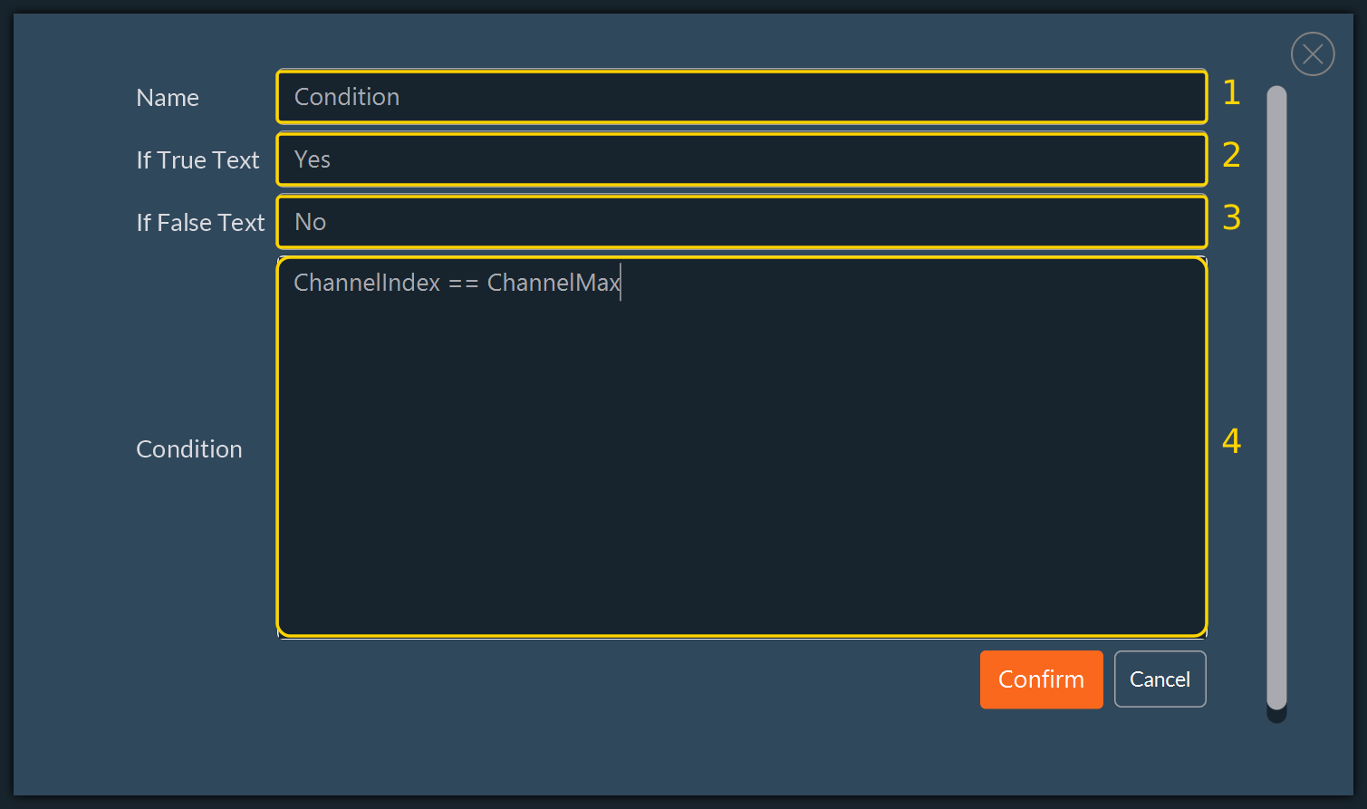
-
-
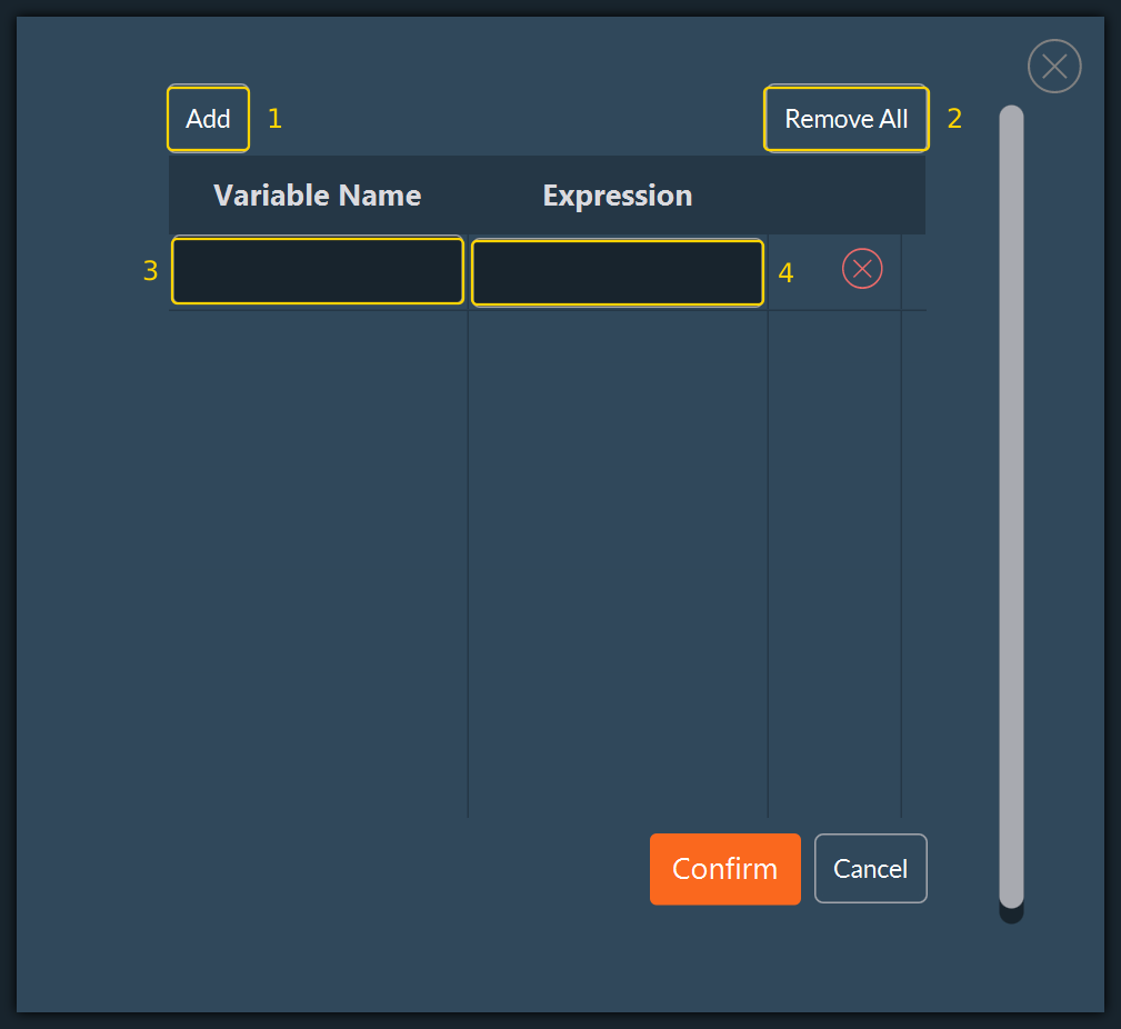
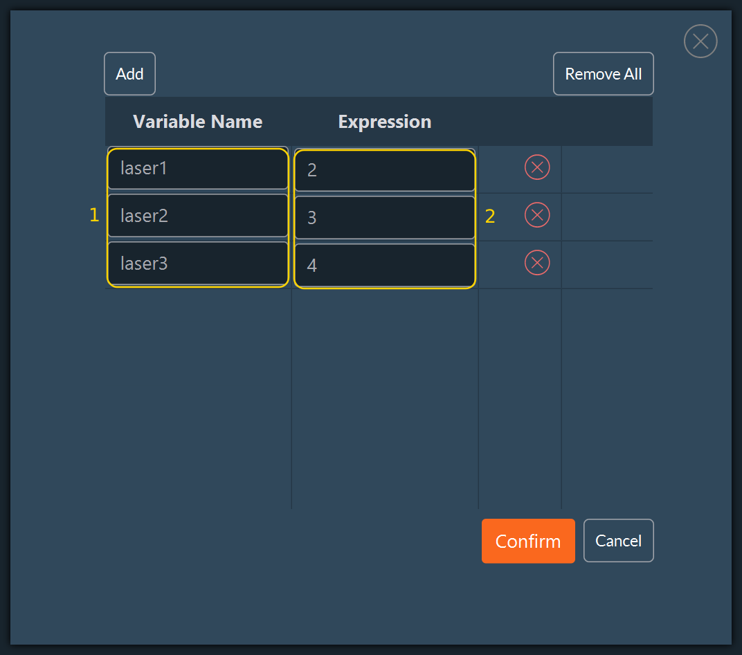
Variable: declares one or more named values, each defined by a Variable Name (3) and an Expression (4). Use Add (1) to append a declaration and Remove All (2) to clear the list. Every expression is re-evaluated each time the flow passes through the block, so a variable may reference dimension indices and previously declared variables, not only constants.
-
Function: stores or modifies a value used by a secondary dimension of a complex acquisition.
-
Prerequisite: place the block before the first block that references the variable.
-
-
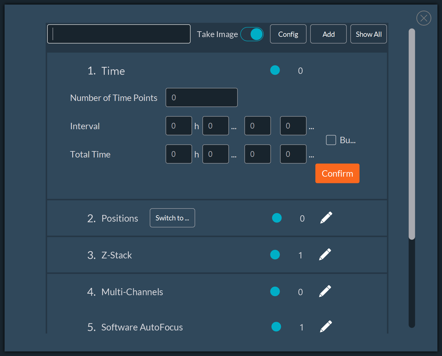
MDA: encapsulates a complete multidimensional sequence in a single block. Its dimensions are configured in the numbered list of the block window: Time, Positions, Z-Stack, Multi-Channels, and Software AutoFocus. Use it when a standard routine is sufficient inside a larger custom protocol, instead of building the equivalent chain of blocks manually.
-
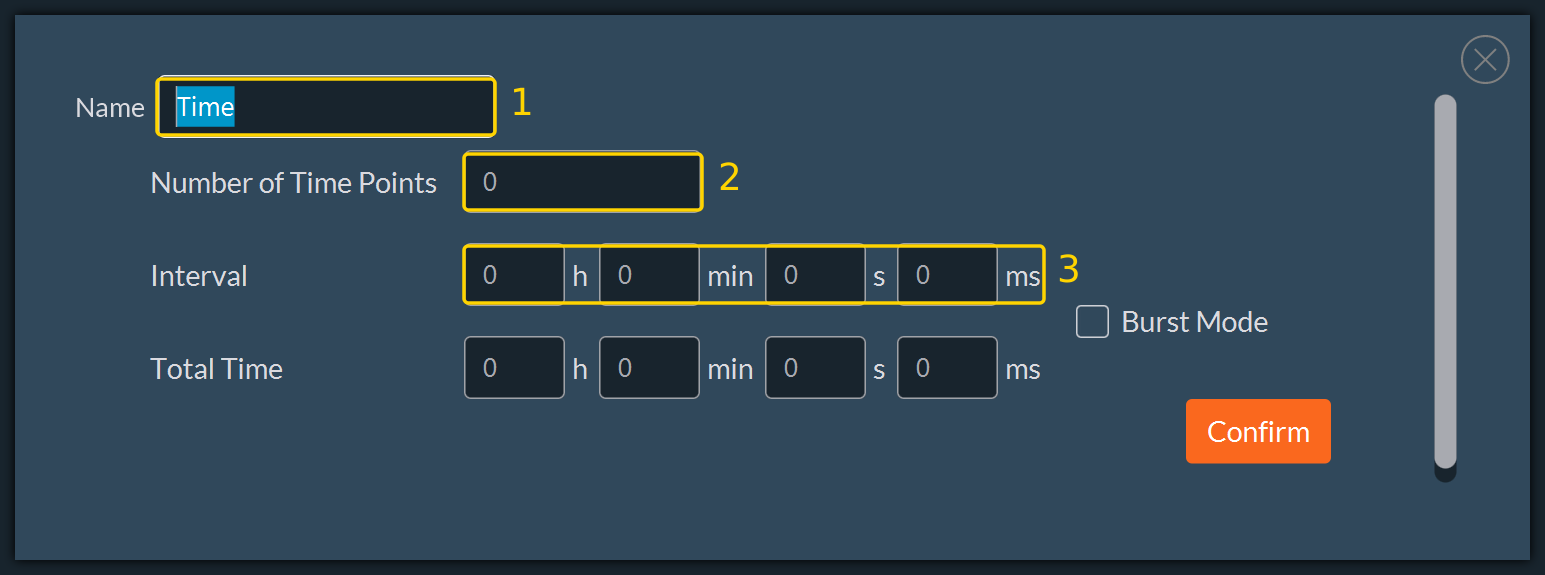
Time: defines a time-lapse dimension from the block Name (1), the Number of Time Points (2), and the Interval (3). Total Time is derived from the two preceding fields.
-
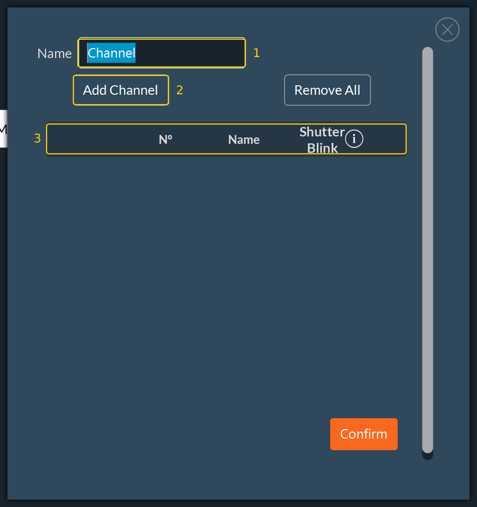
Channel: defines one or several illumination wavelengths. Set the block Name (1), then use Add Channel (2) to append a wavelength to the channel table (3).
-
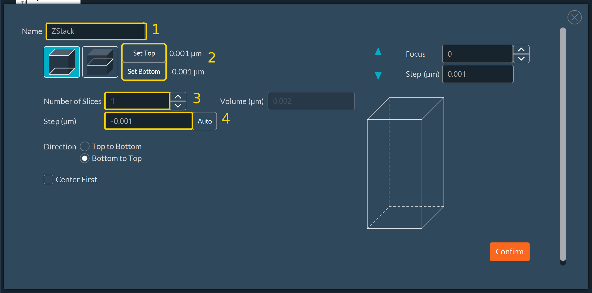
ZStack: defines acquisition along the Z axis from the block Name (1), the top and bottom points set with Set Top and Set Bottom (2), the Number of Slices (3), and the Step (µm) (4).
-
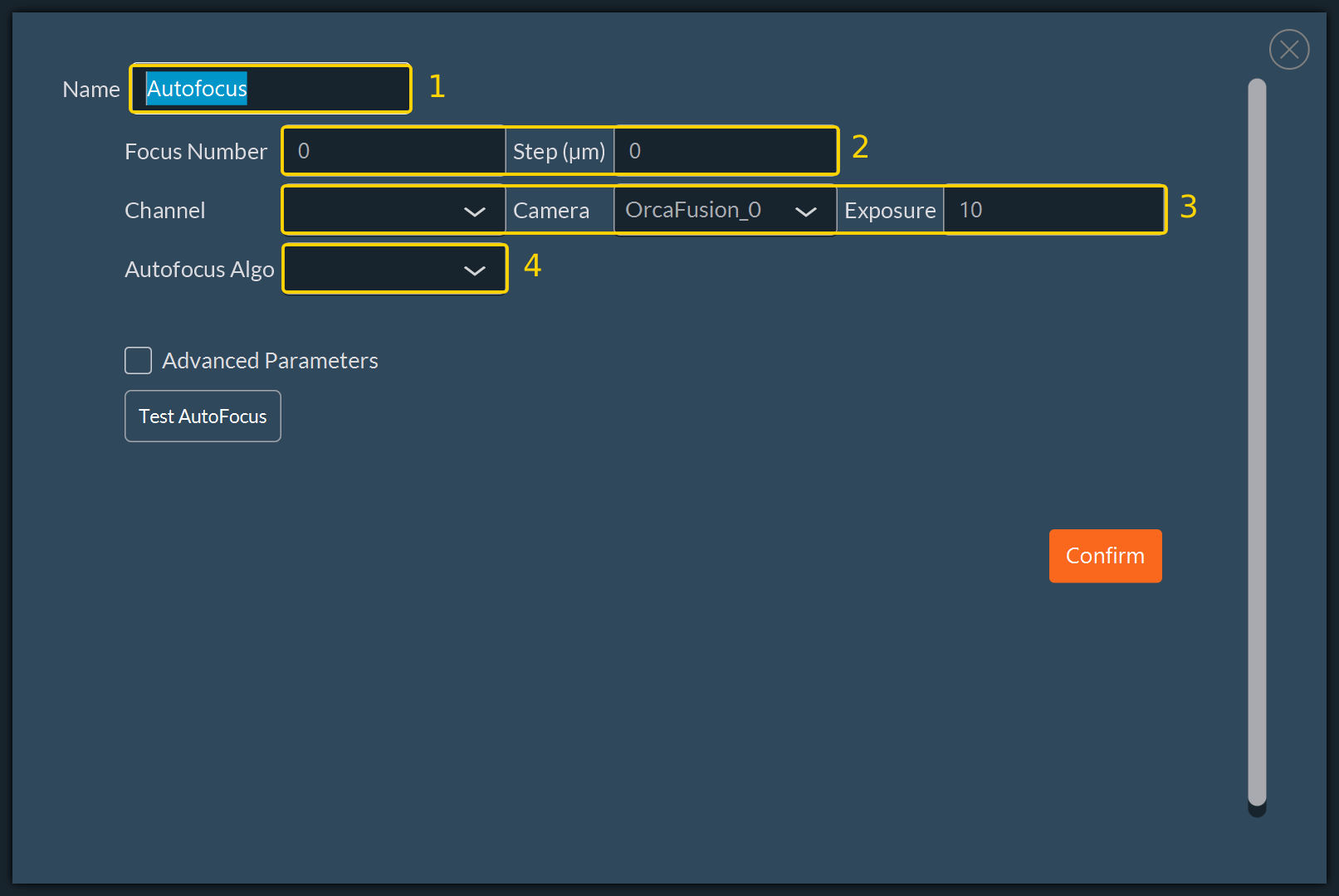
Autofocus: finds the optimal focus plane. Set the block Name (1), the number of sampling images and the travel between them with Focus Number and Step (µm) (2), the acquisition settings Channel, Camera, and Exposure (3), and the Autofocus Algo (4).
-
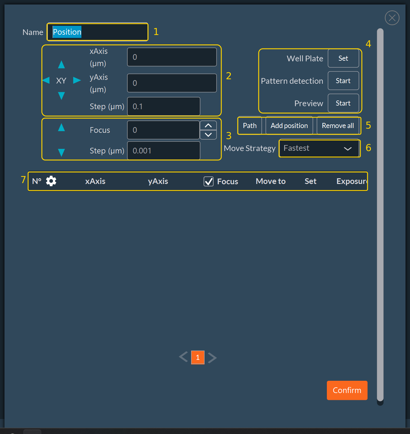
Position: defines the XY stage coordinates visited by the protocol. Set the block Name (1), the XY coordinates and their step (2), and the Focus value and its step (3). The right column groups the Well Plate definition, the Pattern detection, and the Preview (4), the position commands Path, Add position, and Remove all (5), and the Move Strategy (6). Every position registered is listed in the table (7).
-
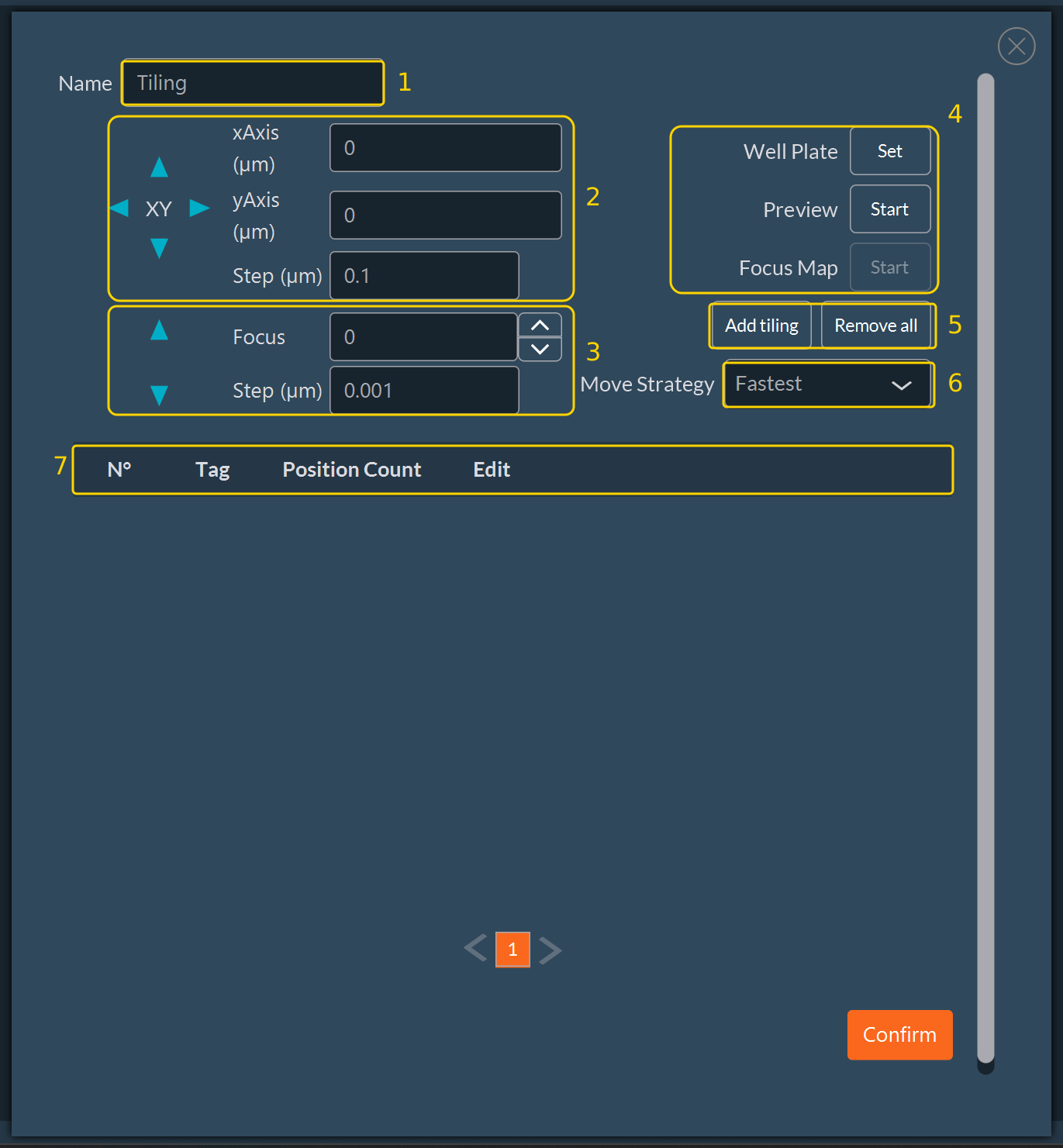
Tiling: generates an image mosaic from adjacent fields of view. Set the block Name (1), the XY coordinates and their step (2), and the Focus value and its step (3). The right column groups the Well Plate definition, the Preview, and the Focus Map (4), the mosaic commands Add tiling and Remove all (5), and the Move Strategy (6). Every mosaic registered is listed in the table (7).
-
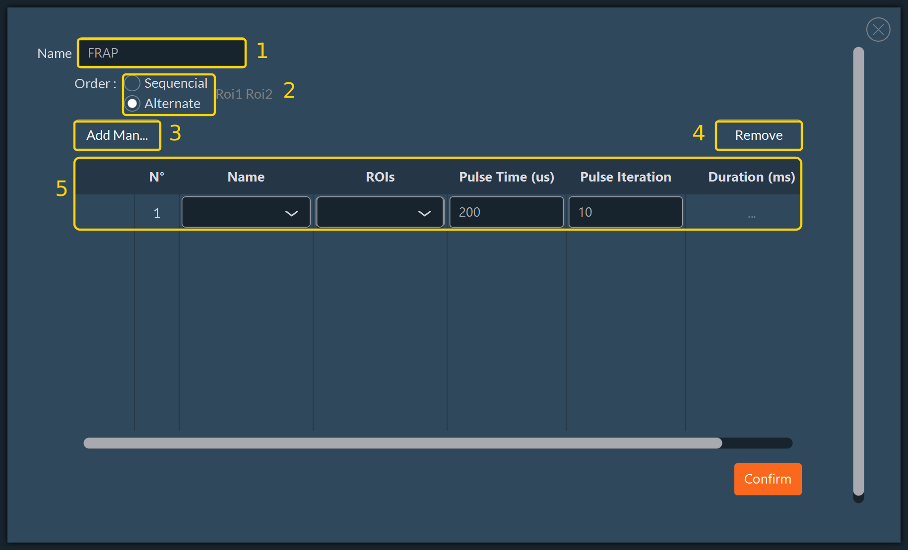
FRAP: optional module block for photobleaching and photoactivation experiments. Set the block Name (1) and the Order in which the regions are illuminated, Sequencial or Alternate (2). Use the manual entry button (3) to append a pulse and Remove (4) to delete the selected one. Each pulse is listed in the table (5) with its Name, ROIs, Pulse Time (us), and Pulse Iteration. Configure the block according to the laser setup.
Important
-
Mandatory unique naming: every block in the workspace must have a unique name. Each dimension block publishes its counters under its own name, so two blocks sharing a name overwrite each other and Condition blocks evaluate the wrong values.
-
Structural errors are flagged, logical errors are not: the workspace marks a block whose links are incomplete, for example a Condition block with an unconnected branch. It does not check the content of an expression. A condition that references a misspelled or undeclared name is only detected when the protocol runs.
-
Silent failure behavior: the Designer does not display pop-up warnings for logical errors. If clicking Start Acquisition produces no action, inspect the links, the block names, and the loop criteria.
Condition and Variable Syntax
Condition and Variable blocks share the same expression language. Expressions are evaluated against the acquisition context, which holds the counters published by every dimension block and the variables already declared. A name that is not present in the context at the moment of evaluation aborts the acquisition with an error, so a Variable block must always be placed upstream of the first block that references it.
Available Names
Each dimension block publishes two names built from the block name:
| Name | Meaning |
|---|---|
[Block Name]Index |
Number of steps already completed in that dimension. It is 0 before the first step and reaches [Block Name]Max once the last step is done. |
[Block Name]Max |
Total number of steps in that dimension: the number of slices, time points, positions, or channels declared in the block. |
A Tiling block publishes three additional names:
| Name | Meaning |
|---|---|
[Block Name]TilingIndex |
Index of the current mosaic. |
[Block Name]TilingNumber |
Total number of mosaics. |
[Block Name]TilingLineIndex |
Index of the current line within the mosaic. |
A Variable block publishes each declared variable under its own name. The value of a variable is itself an expression, re-evaluated every time the flow passes through the block.
Important
-
Names are case-sensitive and must match the block name exactly. A name must start with a letter or an underscore and may contain only letters, digits, and underscores. Dotted names such as
ZStack1.Indexare not valid. -
An MDA block does not publish counters. Its internal Time, Channel, and ZStack dimensions cannot be referenced from a Condition expression. Use separate dimension blocks when the protocol has to branch on their indexes.
Operators and Functions
| Category | Symbols |
|---|---|
| Arithmetic | +, -, *, /, % (modulo), ^ (power) |
| Comparison | ==, !=, >, >=, <, <= |
| Boolean | && (and), \|\| (or), ! (not) |
| Boolean constants | TRUE, FALSE (uppercase) |
| Grouping | ( ) |
The following functions are available. Angles are expressed in radians.
| Function | Description |
|---|---|
sqrt(x), exp(x), ln(x) |
Square root, exponential, natural logarithm |
abs(x), floor(x), ceil(x) |
Absolute value, rounding down, rounding up |
cos(x), sin(x), tan(x) |
Trigonometric functions |
acos(x), asin(x), atan(x) |
Inverse trigonometric functions |
atan(y, x) |
Two-argument arc tangent |
deg(x), rad(x) |
Conversion between radians and degrees |
if(condition, a, b) |
Returns a when the condition is true, otherwise b |
Operator Precedence
Operators are grouped in the following order, from the highest precedence to the lowest. Operators of equal precedence are evaluated from left to right.
| Rank | Operators |
|---|---|
| 1 | !, unary - |
| 2 | ^ |
| 3 | *, / |
| 4 | +, - |
| 5 | % |
| 6 | ==, !=, >, >=, <, <= |
| 7 | &&, \|\| |
Warning
Modulo has a lower precedence than addition and subtraction, which is the opposite of the convention used in most programming languages. TimeIndex - 1 % 2 is evaluated as (TimeIndex - 1) % 2, not as TimeIndex - (1 % 2). Use explicit parentheses whenever % appears next to + or -.
Typical loop and interval expressions:
In the Variable block below, each variable name (1) is paired with the expression that defines it (2). The names laser1, laser2, and laser3 are then available to every downstream Condition block.
Note
Condition examples:
-
ZStack1Index == ZStack1Max: every Z slice declared in the ZStack1 block has been acquired. Use it to close a Z-stack loop. -
PositionIndex == PositionMax: every position declared in the Position block has been visited. Use it to close a position loop. -
TimeIndex % laser2 == 0: the current time point is a multiple of the interval stored in the variablelaser2. Use it to acquire a channel on a subset of the time points. -
A multi-channel loop (e.g., 405, 488, and 638) closes on the same rule:
[Block Name]Index == [Block Name]Max.
Complex Acquisition Examples
Example 1: One Interval Time per Channel
Time-lapse, multi-position, and Z-stack acquisition with four channels — BF, DAPI, GFP, and Texas Red — using a different interval time for each channel.
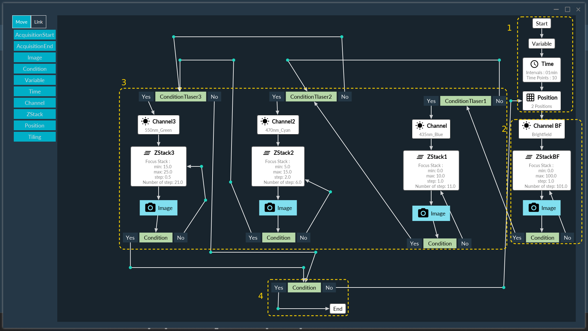
Description: the numbers below match the regions outlined on the flowchart.
-
Initial setup (1)
-
Start the acquisition.
-
Set the variables: declare the interval times used by the time-lapse.
-
Set up the time-lapse: configure the timing parameters.
-
Choose the positions: define the XY coordinates.
-
-
Default sequence: brightfield (BF) (2)
-
Select the first channel (BF).
-
Set up the Z-stack.
-
Acquire the image.
-
Condition: is the Z-stack finished?
-
No: continue the Z-stack acquisition.
-
Yes: proceed to the channel changes.
-
-
-
Channel conditional sequence (3)
-
Laser 1 condition (DAPI): is the current time point a valid interval for DAPI acquisition?
-
Yes: select the DAPI channel, run the Z-stack, and acquire the image.
-
Sub-condition: is the Z-stack finished? If no, continue the acquisition. If yes, proceed to the next channel.
-
No: skip to the second channel.
-
-
Laser 2 condition (GFP): is the current time point a valid interval for GFP acquisition?
-
Yes: select the GFP channel, run the Z-stack, and acquire the image.
-
Sub-condition: is the Z-stack finished? If no, continue the acquisition. If yes, proceed to the next channel.
-
No: skip to the third channel.
-
-
Laser 3 condition (Texas Red): is the current time point a valid interval for Texas Red acquisition?
-
Yes: select the Texas Red channel, run the Z-stack, and acquire the image.
-
Sub-condition: is the Z-stack finished? If no, continue the acquisition. If yes, proceed to the position check.
-
No: skip to the position check.
-
-
-
Position loop and end (4)
-
Condition: are all positions acquired?
-
No: move to the next position, then restart the sequence from step 2.
-
Yes: end the acquisition.
-
-
Example 2
The following protocol combines the same building blocks in a longer branched architecture. It alternates a spinning-disk Z-stack with a widefield channel pair, at seven positions and over 72 time points.
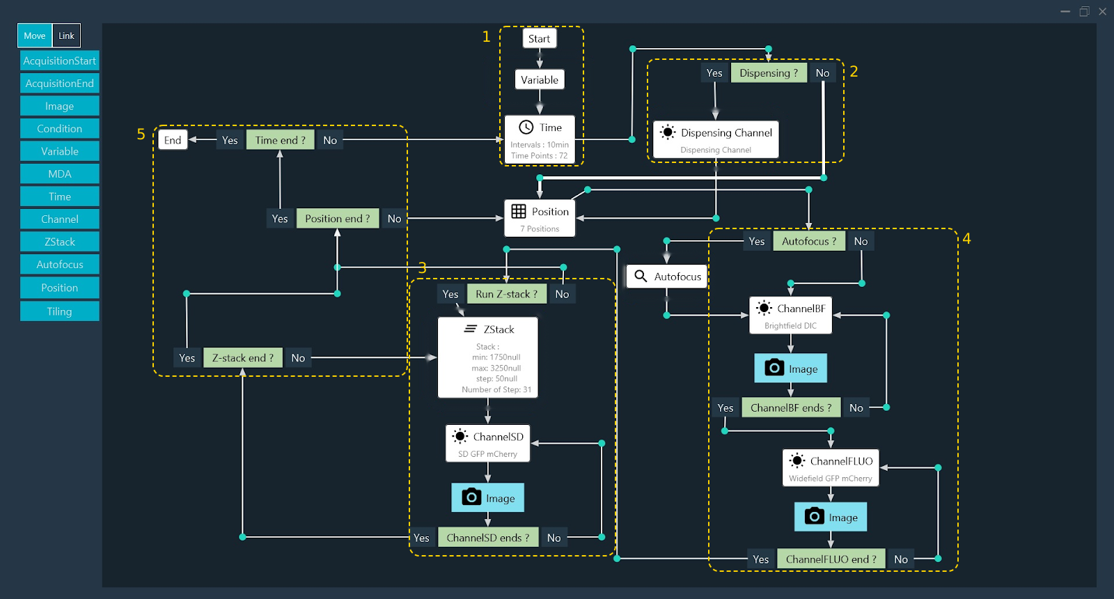
Description:
-
Initial setup (1): start the acquisition, declare the variables, and configure the time-lapse.
-
Dispensing branch (2): a Condition block tests whether a reagent has to be dispensed at the current time point. If dispensing is required, the dispensing channel is selected before the flow reaches the Position block.
-
Spinning-disk sequence (3): a Condition block tests whether the Z-stack has to run. If it does, the ZStack block, the ChannelSD block, and the Image block are executed until the Z-stack loop closes.
-
Widefield sequence (4): an Autofocus condition runs the autofocus when required, then the ChannelBF and ChannelFLUO blocks are acquired in turn, each closing on its own channel condition.
-
Loop exits (5): the Z-stack, position, and time conditions are evaluated in that order. The protocol ends once the last time point has been acquired.
Finalizing Acquisition Settings
Review and Validate the Acquisition Protocol
Once the protocol is built, close the Show Full window to return to the main Designer tab for an overview and final adjustments.
Click Validate to register and verify the design.
Note
If the total image counter remains at 0 after clicking Validate, the flow architecture contains an error. Re-evaluate the block logic and the links.
Data Processing and Saving
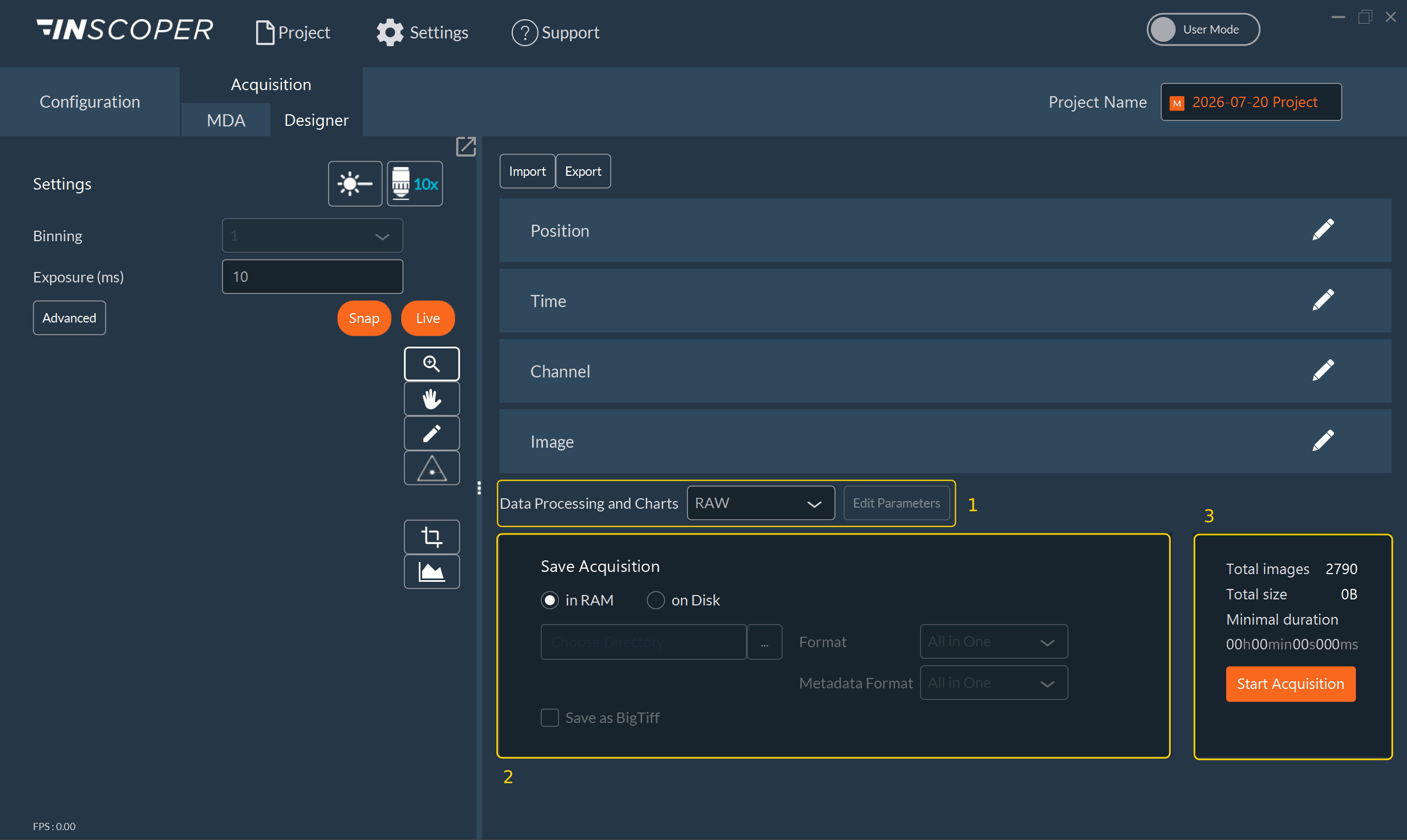
Configure the following before launching the acquisition:
-
The Data Processing and Charts selection (1), which controls real-time image visualization during and after the acquisition. Click Edit Parameters to configure the selected DataProcessor.
-
The Save Acquisition settings (2): the saving location, in RAM or on Disk, and, for a saving on disk, the target directory, the Format, and the Metadata Format.
Note
The summary panel (3) displays the total number of images, the estimated file size, and the minimum duration of the experiment in real time.
Click Start Acquisition (3) to run the experiment.