Z-stack
Use the Z-Stack dimension to capture volumetric data by acquiring a series of sequential optical slices along the Z-axis.
Configuring a Z-Stack
Configure the volumetric boundaries using one of three primary methods:
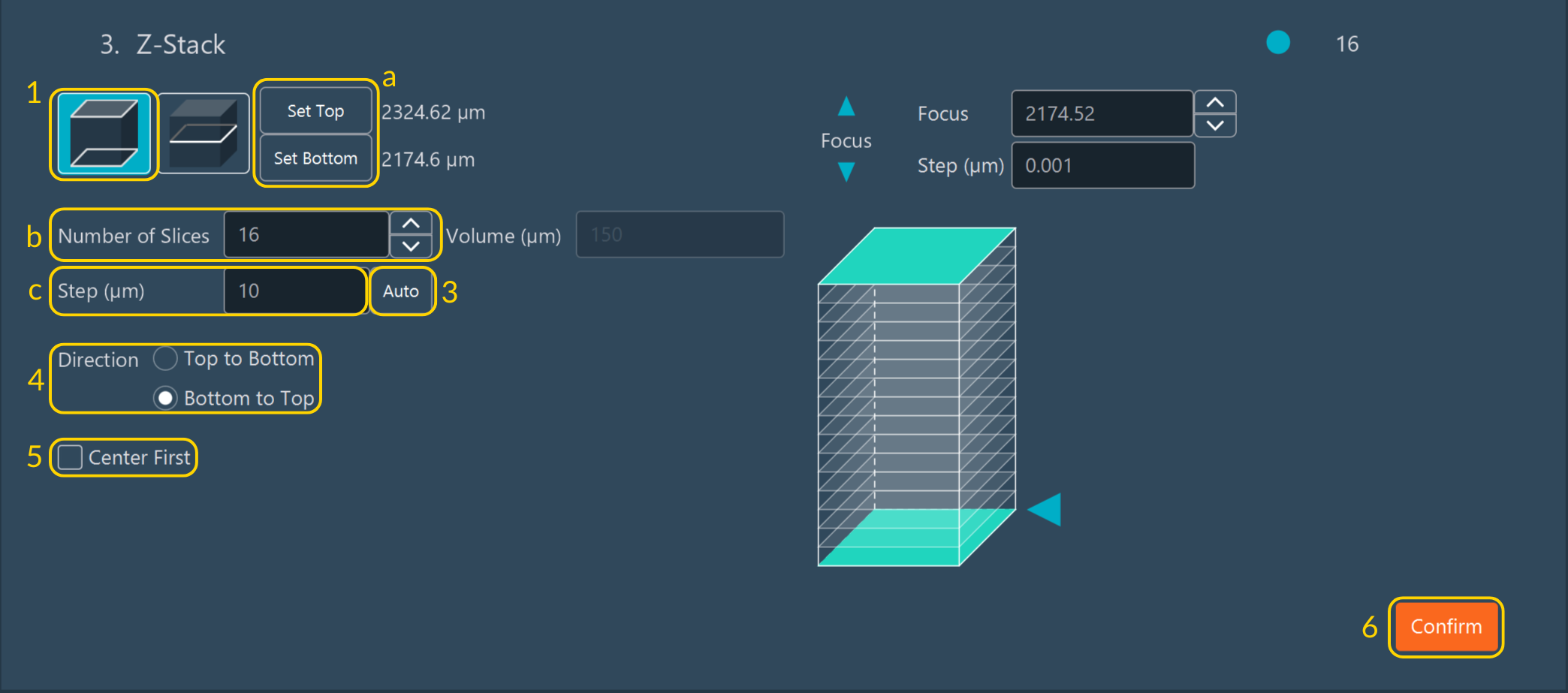
Method 1: Define Top and Bottom Limits
- Move the stage to the desired upper and lower focal limits, then click Set Top and Set Bottom to establish the boundaries.
- Specify the number of slices (focal planes) within this volume.
- Set the step size (in µm) between adjacent focal planes.
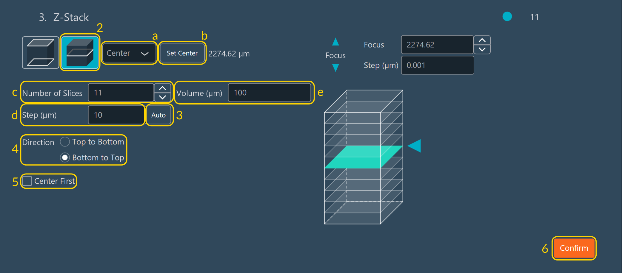
Method 2: Define via a Reference Plane
-
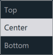
Select whether the current live focal point represents the center, top, or bottom of the intended Z-stack.
-
Click the corresponding registration button (Set Center, Set Top, or Set Bottom) to log the current focal plane as the anchor.
- Specify the total number of slices.
- Set the step size (in µm).
- Alternatively, define the volume depth of the Z-stack (in µm). The software computes the remaining variables automatically.
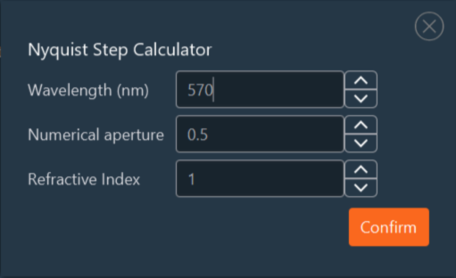
Method 3: Nyquist Auto-Calculation
Use this method to automatically compute the optimal step size for maximum 3D optical resolution without oversampling the volumetric data. Click Auto to generate the ideal Nyquist Z-sampling rate.
- The software calculates the ideal physical step size based on the longest emission wavelength configured in the multi-channel parameters.
- These values remain editable. Manually override the calculated step size or tune the inputs, such as the emission wavelength, the objective's numerical aperture (NA), and the refractive index (RI) of the immersion medium.
- Click Confirm to save the computational settings.
Finalizing Z-Stack Parameters
Once the geometric volume is defined, set the execution parameters:
- Select the acquisition direction: either Top to Bottom or Bottom to Top.
-
Enable Center First to force the sequence to begin acquisition at the central focal plane.
Tip
This setting is required when utilizing hardware-based autofocus systems (e.g., PFS, Definite Focus) to ensure they anchor correctly before sweeping the volume.
-
Click Confirm to save the Z-stack configuration block.
Tip
Use the interactive Z-stack diagram to verify the setup — drag the blue arrow or click the diagram to drive the stage and preview the stack bounds.
Important
When configuring a Z-stack from a center reference plane, the Volume, Step, and Number of Slices fields are mathematically linked. Adjusting one automatically recalculates the others. If the Positions dimension is active and the Z-axis override is enabled for a specific position, that local spatial focus value overrides the global center coordinate of the Z-stack.