Time Gated Domain FLIM (fastFLIM)

fastFLIM is a hardware and software solution designed to measure mean fluorescence lifetime using a widefield, camera-based microscope architecture. fastFLIM measurements combine with the other imaging dimensions, including Multi-positions, Tiling mosaics, Multi-channel overlays, and Z-stacks.
Unlike traditional point-scanning FLIM (e.g., TCSPC), which is typically slow, fastFLIM is a camera-based FLIM technique that employs a time-domain approach combined with a time-gated image intensifier. This captures the lifetime of the entire field of view simultaneously (or rapidly via spinning disk), providing significantly higher acquisition speeds and minimal phototoxicity. This makes it highly effective for observing rapid biological dynamics and biosensors in living cells.
Hardware Configuration
The Configuration tab gives access to the FLIM timing and gating parameters:
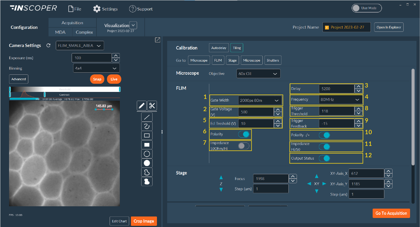
- Gate Width: Specifies the absolute duration of the temporal detection window (gate).
- Gate Voltage: Sets the multi-channel Plate (MCP) potential voltage, which directly controls the internal signal amplification (gain) of the intensifier.
- Delay: The temporal offset (in picoseconds) applied relative to the pulsed laser synchronization signal.
- Frequency: The operational repetition rate of the central delay generator.
- ECL Threshold: Sets the electrical noise floor threshold for the input synchronization signal routed to the intensifier.
- Polarity: Configures the detector logic to correctly identify the leading or trailing edge of the delay generator's synchronization pulse.
- Impedance: Adjusts electrical impedance matching to ensure artifact-free signal detection.
- Trigger Threshold: Sets the electrical noise floor threshold for the input synchronization signal routed to the delay generator.
- Trigger Feedback: (Specific to legacy delay generator models). Displays a diagnostic value verifying lock synchronization between the delay generator and the pulsed laser. Optimal operational values hover near 0, safely within a [-100, +100] operational range.
- Polarity (-/+): Configures the delay generator logic to correctly detect the laser's physical synchronization pulse.
- Impedance (Hi/50Ω): Adjusts electrical impedance matching specifically for the laser synchronization line.
- Output Status: Manual override for the optical shutter control.
Note
The visibility and editability of specific parameters adapt dynamically based on the specific intensifier and gating hardware model recognized by the system.
Autodelay Pulse Calibration
Important
Before initiating a FLIM experimental sequence, execute an Autodelay calibration. This step synchronizes the pulsed laser excitation with the initial temporal gate opening, ensuring accurate photon capture and reliable lifetime calculations.
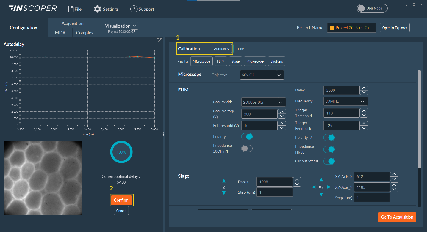
- Click Autodelay to launch the automated hardware calibration protocol.
- Wait for the software algorithm to calculate the optimal temporal offset. Once displayed, click Confirm. This calibrated picosecond value will automatically populate the master Delay field in the Configuration tab.
Sequence Acquisition
With the hardware configured and calibrated, proceed to the Acquisition tab to build the imaging sequence.
Configure the imaging channels in the Multi-channel dimension. Define both the widefield fluorescence channels and the FLIM measurement channels.
In the FLIM dimension panel, the available controls depend on the number of active FLIM channels:
Simple Mode
This mode activates automatically when only a single FLIM channel is present in the sequence.
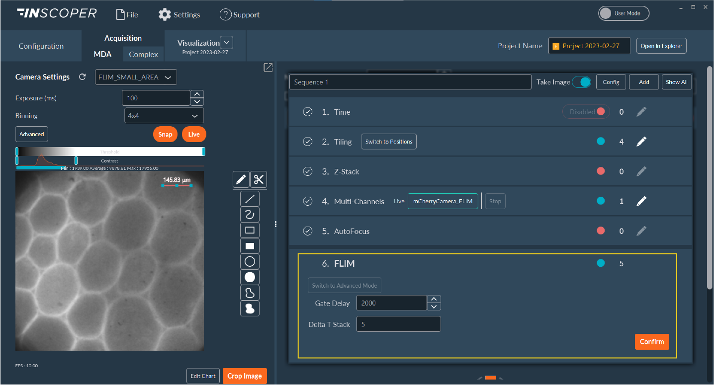
- Gate Delay: The temporal shift between successive measurement gates along the decay curve.
- Delta T stack: The number of time points to acquire for the complete FLIM decay curve.
Advanced Mode
This mode activates automatically when multiple FLIM channels are configured in the sequence. It exposes per-channel timing parameters.
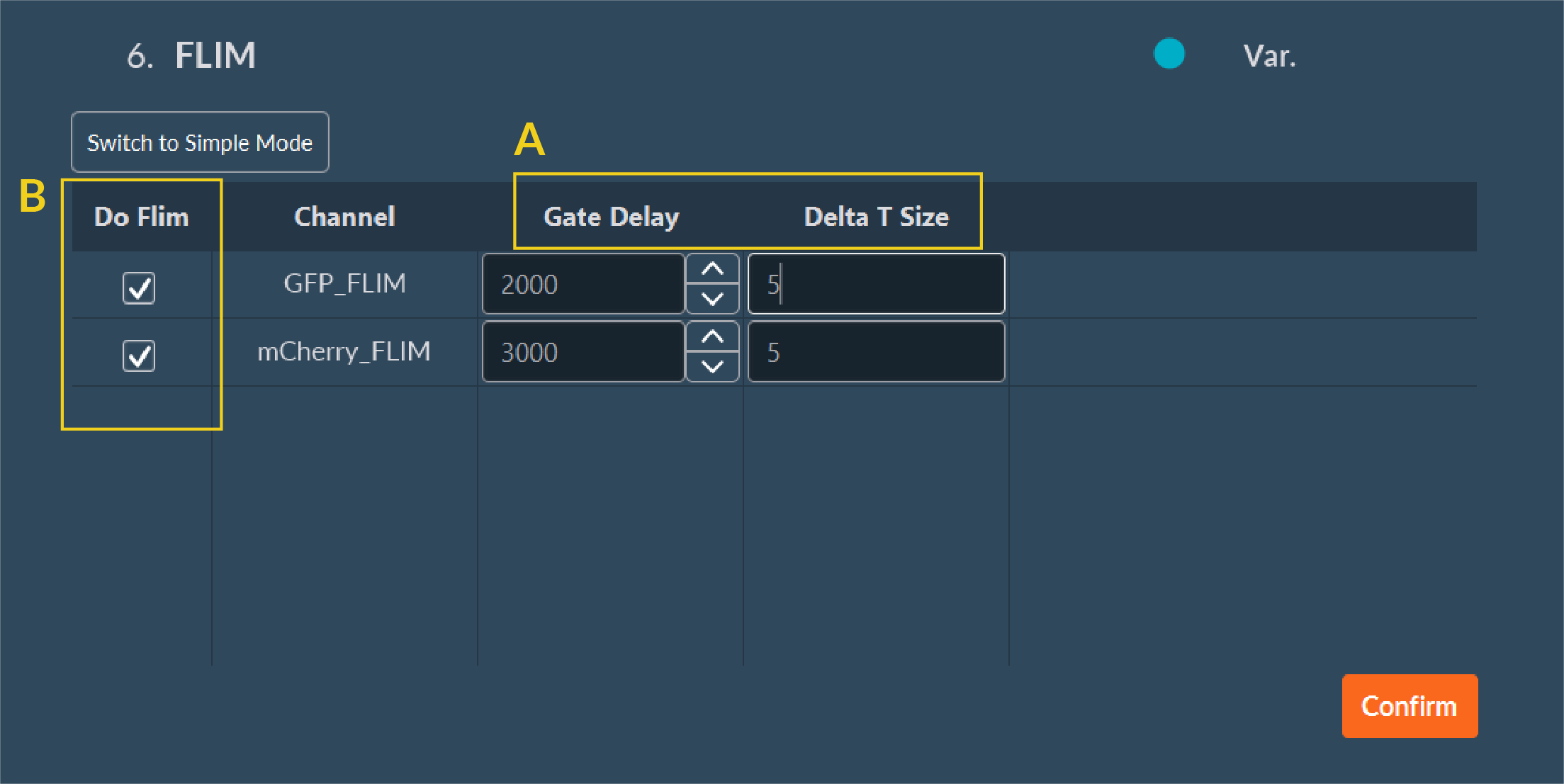
- A: Define an independent Gate Delay and Delta T Size for each channel.
- B: Enable or disable the FLIM measurement per channel with the Do Flim checkboxes.
Finalizing Acquisition
Once the FLIM timing parameters are set, click Confirm on the dimension module. To complete the data routing:
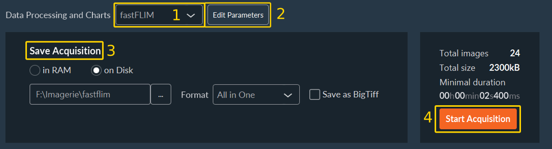
- Navigate to the Save menu. Select fastFLIM from the Data Processing and Charts computation drop-down menu.
-
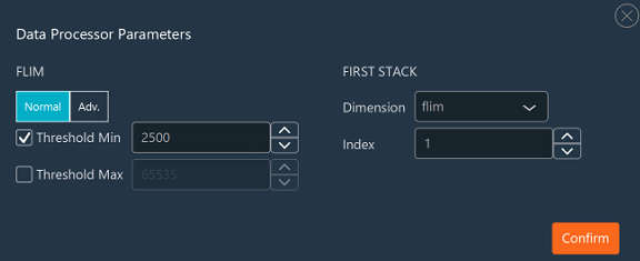
Click Edit Parameters to define the absolute minimum and maximum Intensity Thresholds (photon counts) required for valid pixel-wise FLIM calculation.
- Normal : Define the absolute minimum and maximum Intensity Thresholds (photon counts) required for valid pixel-wise FLIM calculation.
- Advanced : Define by channel different minimum and maximum Intensity Thresholds (photon counts) required for valid pixel-wise FLIM calculation.
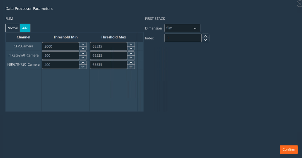
- Click Confirm. (Pixels below this threshold are excluded from the decay fit).
- Normal : Define the absolute minimum and maximum Intensity Thresholds (photon counts) required for valid pixel-wise FLIM calculation.
-
Specify your absolute destination save folder path.
- Click Start Acquisition to initiate the sequence.
Data Visualization
The Visualization tab provides FLIM analytical results computed at the end of the acquisition. It displays calculated FLIM maps alongside raw sensor intensity, integrated lifetime distributions, and point-wise intensity decay curves.
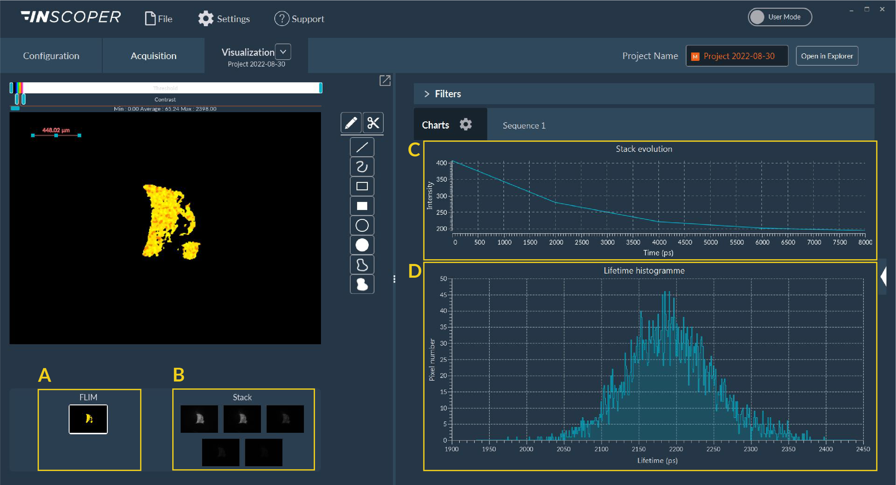
- A: The pseudo-colored, computed FLIM image map.
- B: The time-gated intensity images used for the decay calculation.
- C: The plotted intensity decay curve for the selected pixel or ROI.
- D: The global pixel lifetime distribution histogram.
All generated multi-dimensional images and statistical charts are saved automatically to your specified destination folder upon compute completion.