TIRF
Total Internal Reflection Fluorescence
Optical Calibration
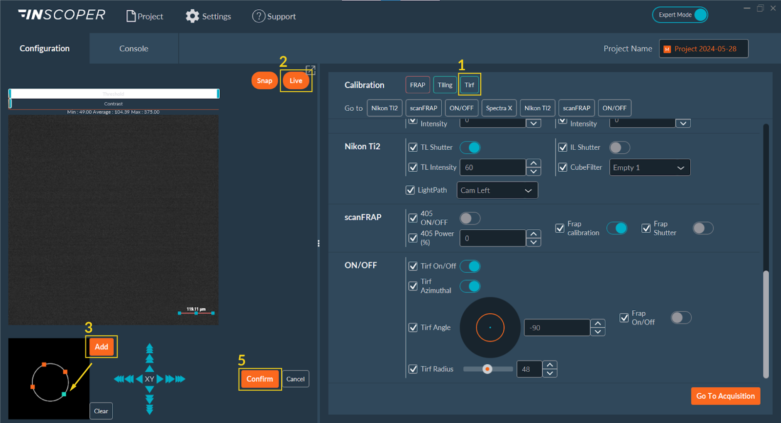
- Navigate to the Calibration section and click TIRF.
- Enable the Live camera feed to observe the sample.
- Click Add to insert a calibration point into the schematic field of view. This blue control point corresponds to the TIRF laser position. Drag this point radially to adjust the laser incidence angle until you achieve critical angle TIRF illumination (evidenced by the loss of out-of-focus background fluorescence).
- Repeat the coordinate placement process to define additional calibration positions if needed for different sample topologies or wavelengths.
- Click Confirm to save the spatial calibration matrix.
- Repeat this angular calibration protocol for each discrete laser wavelength intended for TIRF imaging, as critical angles vary with excitation wavelength.
Configuration
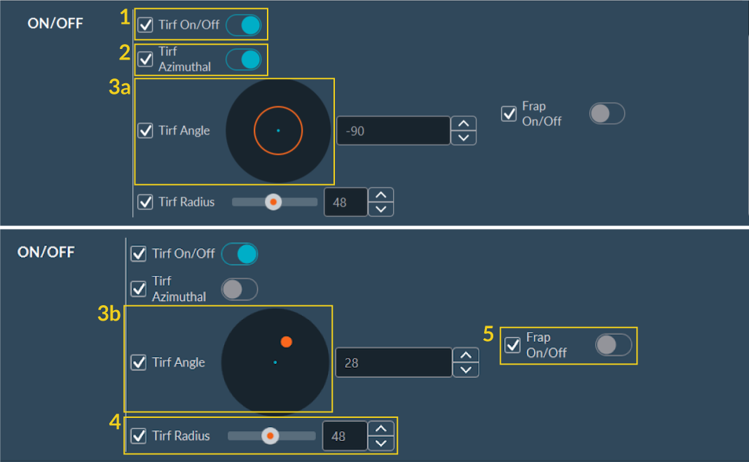
- Activate TIRF: Toggle the switch to enable or disable TIRF mode hardware control.
- TIRF Azimuthal: Toggle TIRF Azimuthal to enable circular illumination, minimizing interference fringes and uneven illumination.
- Option:
- a. Activated: The interface displays a diagram of the circular laser scanning pattern at the currently set TIRF angle.
- b. Deactivated: The interface displays a single laser position (orange dot). Specify its coordinates using the TIRF Angle parameter field.
- TIRF Radius: Adjust the spatial radius to set the laser incidence angle at the objective lens aperture. This control determines the illumination regime: Widefield (Epi), Highly Inclined and Laminated Optical Sheet (HILO), or TIRF.
- FRAP: Toggle the corresponding switch to activate the targeted photobleaching (FRAP) function.
Creating a TIRF Channel
Save the spatial parameters (Azimuthal mode, Angle, and Radius) to the designated TIRF channel preset in the Configuration tab to properly execute automated TIRF imaging.
Sequence Acquisition
Select the saved TIRF channel to perform a TIRF acquisition during the multi-dimensional sequence.