Imaging Software Advanced Settings
Each control in the Imaging Software layout has advanced settings that determine how the Imaging Software displays and constrains it: the label, the widget type, the numeric bounds, the unit, and the visibility rules.
The Configurator derives these settings from the hardware description when it generates the layout. Override them only where the derived values do not match the instrument.
Opening the advanced settings
- Click Next to open the layout stage.
- Hover over the control in its category card. A gear icon appears on the control.
- Click the gear icon, or double-click the control. The Edit Parameter - control name window opens.
- Change the settings, then click Confirm to apply them, or Cancel to discard them.
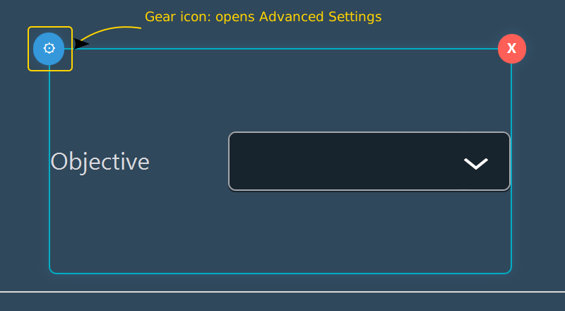
The window is modal and applies to a single control. For a stage, the window covers the X and Y axes together and adds a field for the stage name.
The window has three sections: General, Display, and Advanced.
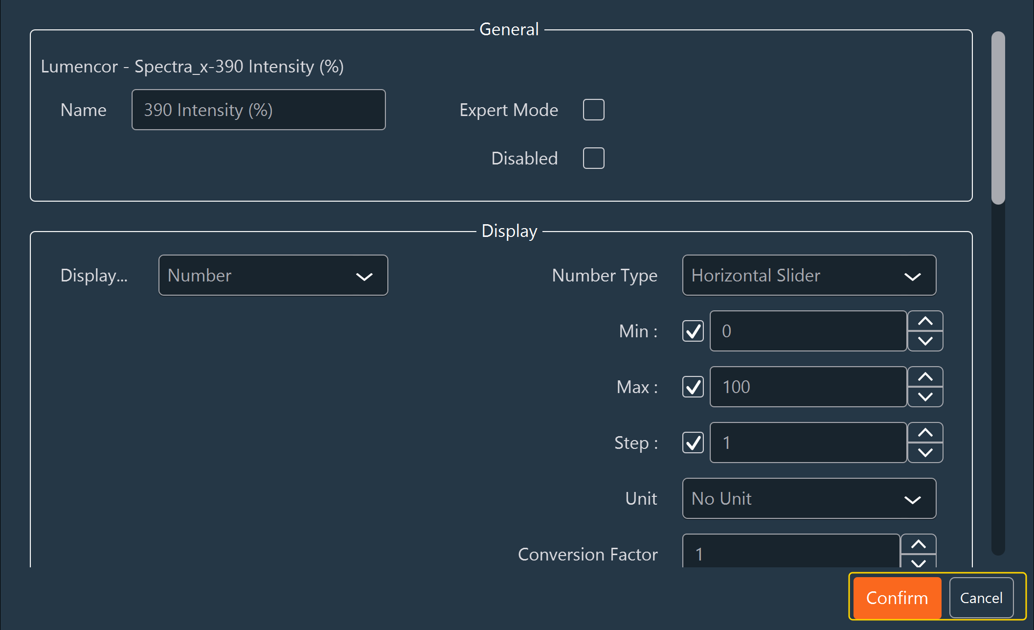
General
The top of the section shows the full name of the parameter: the device name followed by the parameter name. Quote this name when reporting a problem.
| Setting | Description |
|---|---|
| Name | The label of the control in the Imaging Software. |
| Expert Mode | Restricts the control to Expert Mode. The control is hidden in User Mode, the standard mode of the Imaging Software. |
| Disabled | Displays the control but prevents the user from changing its value. |
Display
Display Type sets the widget that the Imaging Software uses for the control. Each type shows its own fields when selected.
| Display type | Use for |
|---|---|
| Select | A parameter with a fixed set of named states, such as a turret position or a filter wheel position. |
| Switcher | A parameter with two states, such as a shutter. |
| Number | A continuous or stepped numeric parameter, such as a position, an intensity, or an exposure time. |
| Text | A read-only text parameter. This type has no further settings. |
Select
| Setting | Description |
|---|---|
| Select Type | Combo Box (drop-down list), Toggle Button (two-state switch), or Radio Button (one button per state). |
| Value table | One row per state: the Value sent to the hardware and the Display Value shown to the user. Click Add Value to append a row, and click the red cross to remove one. |
Filter wheel
For a five-position filter wheel with indices 0 to 4, select Combo Box and enter the following values.
| Value | Display Value |
|---|---|
| 0 | DAPI |
| 1 | GFP |
| 2 | YFP |
| 3 | Cy3 |
| 4 | Cy5 |
Switcher
| Setting | Description |
|---|---|
| Switcher Type | Switcher (two-state switch) or Button (pair of labeled buttons). |
| Open Value, Close Value | The values sent to the hardware for each state. |
| Open Name, Close Name | The labels shown for each state. Only the Button type uses them. |
Number
| Setting | Description |
|---|---|
| Number Type | Number Field Only, Vertical Joystick, Theta Joystick, Horizontal Slider, Vertical Slider, or Potentiometer. |
| Min, Max, Step | The bounds and increment of the control. Select the checkbox next to a field to override its value. When the checkbox is cleared, the value from the hardware description applies. |
| Unit | No Unit, Distance, or Time. The Imaging Software formats the value according to the Distance Unit or Time Unit set in Settings > Edit Settings. |
| Conversion Factor | The multiplier between the value displayed to the user and the value sent to the hardware. See Conversion factor. |
| Number Format | The display format of the value, which sets the number of decimal places. |
Some number types have additional fields.
| Number type | Additional fields |
|---|---|
| Horizontal Slider, Vertical Slider | Log Mode and its Center Value, Slider Length, Slider Visible Export Mode Only, and Color. |
| Vertical Joystick, Theta Joystick | Joystick Name, which groups the axes shown on the same joystick. |
| Potentiometer | Angle Length Sub Device Id and Radius Percent Sub Device Id: the parameters controlled by the angle and the radius of the widget. |
Warning
Min, Max, and Conversion Factor determine the values sent to the hardware. An incorrect bound allows the Imaging Software to send the instrument to a position it cannot reach. Check these values against the hardware manufacturer's documentation.
Conversion factor
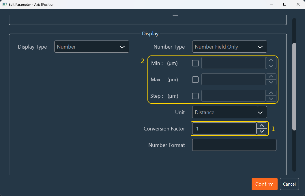
Some distance devices require a manual conversion factor.
- Enter the factor in Conversion Factor (1).
- Leave Min, Max, and Step (2) at their original values.
- Click Confirm.
To check the result, save the configuration and load it in the Inscoper Imaging Software.
Advanced
| Setting | Description |
|---|---|
| Channel Extra Param | Also offers the control as an additional channel-level parameter in the Imaging Software. The control keeps its position in the layout. |
| Acquisition Extra Param | Also offers the control as an additional acquisition-level parameter. |
| Tooltip | The text shown when the user hovers over the control. |
| State Changed Message | The message shown when the value of the control changes. Use it to warn the user of a change they must know about, such as a switched beam path. |
Batch editing
To change the Expert Mode, Disabled, Channel Extra Param, or Acquisition Extra Param setting of several controls at once:
- In the layout editor, Ctrl-click the controls to select them.
- Right-click the selection and click Batch Edit.
- For each setting, choose Yes, No, or No Change, then click Confirm.
Settings left at No Change keep the individual value of each control.