ILDA (MaxiIlda)
This page applies only when a MaxiIlda device is imported. It covers the initial setup in the configuration wizard and the Advanced Ilda Parameters window, with its Ilda Functions, Laser, Frap Mode, Tirf Mode, and Illumination Mode tabs.
Configuring the device in the wizard
-
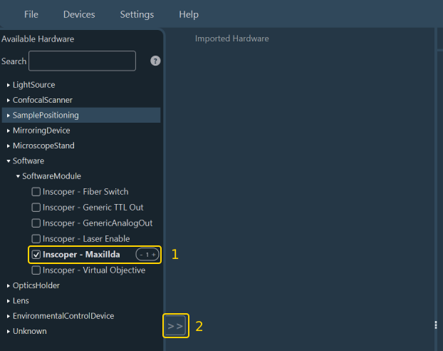
In the hardware importation panel, select Inscoper - MaxiIlda under Software > SoftwareModule (1), then click >> (2) to import it.
-
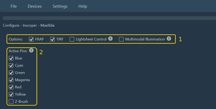
On the Configure step, select the illumination functions of the system under Options (1):
- FRAP
- TIRF
- Lightsheet Control: select this when the ILDA is connected to a light sheet system.
- Multimodal Illumination: select this to switch between illumination modes (FRAP, TIRF, and spinning disk) on a multimodal system. It is required when the system includes both FRAP and a spinning disk module.
-
Under Active Pins (2), select the color and intensity pins in use on the ILDA connector.
-
On the Set Connection step, link the MaxiIlda to the Device Controller, as described in Connections.
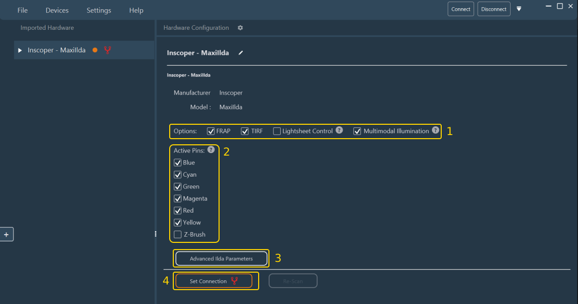
Once the wizard is complete, select the device in the Imported Hardware tree to review its configuration. The device view repeats the Options (1) and Active Pins (2) sections, and adds the Advanced Ilda Parameters button (3) and the Set Connection button (4).
Advanced Ilda Parameters
Click Advanced Ilda Parameters (3) to open the window that assigns the parameters of each mode. Most fields are filled in automatically from the hardware description of the devices already imported and tagged: interpoint distance, pulse time, TIRF angle and penetration depth, fire preview, and the active channels of each mode. A mode only becomes active once the parameters it needs are present and correctly tagged, which is a consequence of the guided-selection step. Modify or complete these assignments at any time.
Laser tab
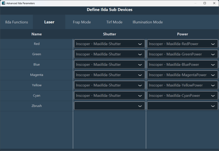
Laser power and shutter are only assigned automatically when the name of the laser contains a recognized color (red, green, blue, magenta, yellow, or cyan) that matches a tagged parameter. If the name of a laser does not match, or if the assignment is incorrect, set Power and Shutter manually from the drop-down lists of this tab.
Calibration discriminants
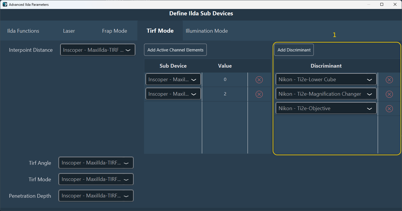
A discriminant is a parameter whose state changes which calibration applies. For example, changing the filter cube or the objective changes the calibration that the mode must use. Each discriminant added to the table requires one calibration entry per state of that parameter (each cube, each objective, and so on).
The Frap Mode, Tirf Mode, and Illumination Mode tabs each carry a Discriminants table (1). Click Add Discriminant to add a row, and the red cross of a row to remove it. The table is pre-populated as matching parameters are added to the configuration:
| Tab | Pre-populated with |
|---|---|
| Frap | Filter cube |
| Tirf | Objective, filter cube, magnification and de-magnification lenses, and filter wheel |
| Illumination | Nothing. Add discriminants manually if the calibration must vary with one of these parameters. |
An empty table means that the calibration is not split along any parameter.
Frap tab: fire preview and camera calibration
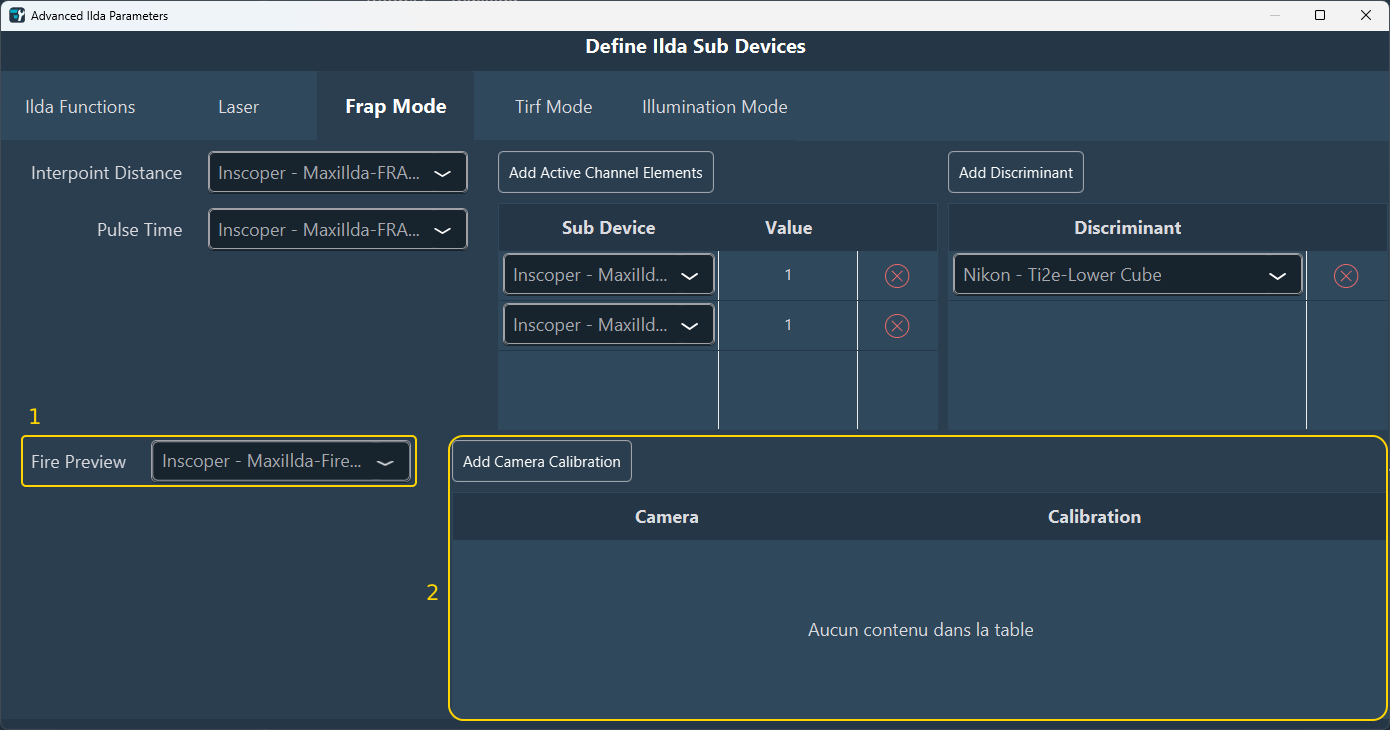
The Frap Mode tab additionally offers two optional settings:
- Fire Preview (1): The parameter that enables the fire preview function.
- Camera Calibration (2): A manually edited table, with one row per camera and its calibration value. Click Add Camera Calibration to add a row.
Terms
- ILDA
- The galvanometer-based illumination modules, Ilas and Starscan. When such a module is imported, its device view offers the illumination modes it supports, together with an Advanced Ilda Parameters section.
- Illumination Mode
- The illumination mode selected on a multimodal system: Frap Mode, Tirf Mode, ROI Mode, or Illumination Mode. Each mode is enabled by its Active checkbox, and each declares the Active Channel Elements that identify the channel it applies to.
- Interpoint Distance
- The distance between two successive points of a scan.
- Pulse Time
- The time between two successive points of a scan, that is, the interval between two galvanometer instructions.
- Fire Preview
- The parameter that enables the fire preview function, the continuous scanning of an ROI.
- Tirf Angle
- The position of the point, or of the arc, on the circle described by the galvanometers.
- Penetration Depth
- The angle of the laser at the lens outlet, which sets the depth of penetration of the evanescent field.
- Scan Mode
- The parameter that switches the module into scanning operation, with its ON and OFF values.
See also: Configuring a device, Calibration.