Configuring a Device
Use this page to declare which functions of an imported device are in use, supply the values those functions require, and read the status markers in the Imported Hardware tree.
This stage follows hardware importation and precedes connections.
Guided selection
The Configurator works by selection, not by deletion. Each device presents a configuration view supplied by the Device Controller firmware. This view offers the functional choices the model supports, such as modules, optical paths, and control modes. From these choices, the Configurator derives which parameters belong to the configuration and which connections they require.
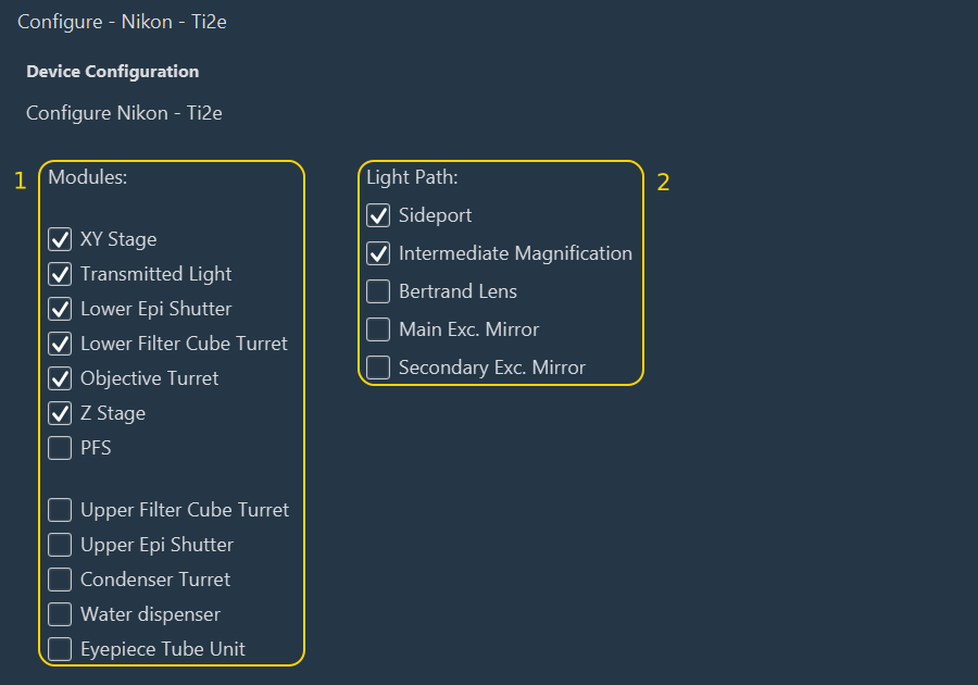
On a Nikon Ti2e inverted microscope stand, for example, the view groups its choices under Modules (1) and Light Path (2). Selecting Objective Turret under Modules adds the turret control functions and the connection that carries them. Clearing the checkbox removes both.
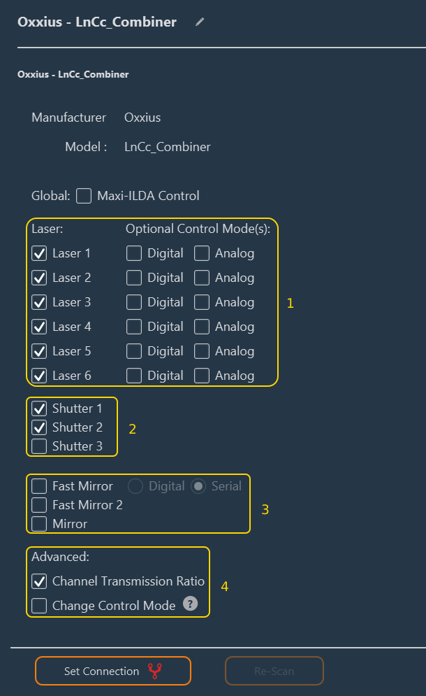
The controls offered depend entirely on the model. A laser combiner, for instance, exposes per-laser control modes (1), shutters (2), mirrors (3), and an advanced section (4).
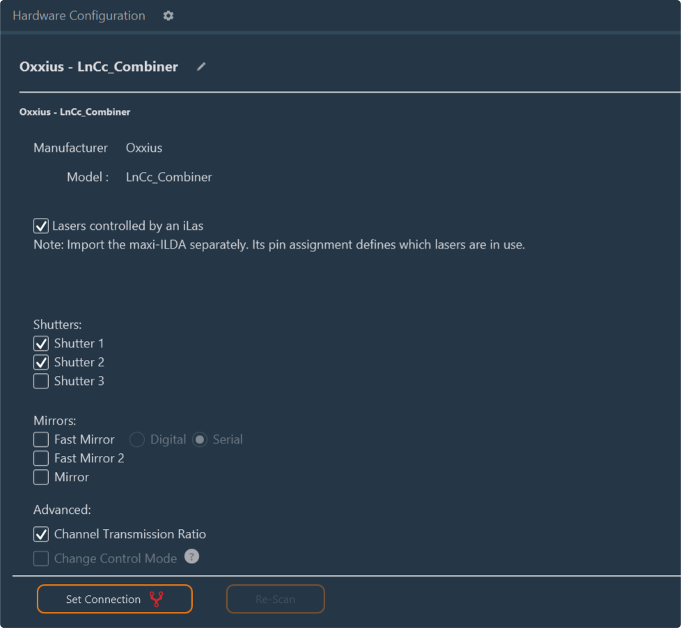
Tip
Where a choice is not self-explanatory, a help icon appears beside it, as for Change Control Mode (4). Hover over the icon to read the description supplied by the firmware.
The device view
Select a device in the Imported Hardware tree to open its view.
| Element | Purpose |
|---|---|
| Title and pencil icon | The name of the device in this configuration. Click the pencil to rename it. Names must be unique within a configuration. |
| Manufacturer, Model | Read-only identification, taken from the hardware description. |
| Configuration controls | The guided-selection controls described above. |
| Set Connection | Opens the connection view restricted to this device. |
| Re-Scan | Interrogates the physical device and removes the functions it does not report. Available only when the Device Controller is connected and the device answers. |
Function groups
Expand a device (1) in the tree to reveal its groups (2). A group corresponds to one function of the instrument, such as a turret, a shutter, a focus axis, or a stage axis. Select a group to open its parameters.
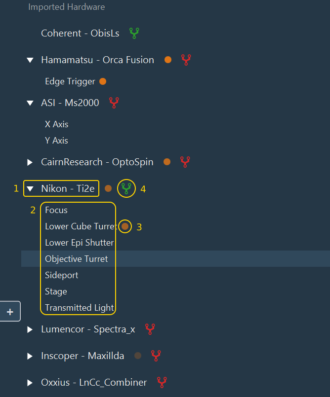
The groups that appear depend on what you selected in the device view. Clearing Objective Turret in the Nikon Ti2e view, for example, removes the Objective Turret group from the tree.
Status markers in the tree
Two kinds of marker appear beside the entries: the orange dot (3) and the connection icon (4).
| Marker | Meaning |
|---|---|
| Green connection icon | Every connection this device requires is defined. |
| Orange connection icon | Some, but not all, of the required connections are defined. |
| Red connection icon | None of the required connections are defined. See Connections. |
| Orange dot | At least one required startup value is missing, a turret group still has an unfilled slot, an ambiguous element has no role assigned, or a camera has no valid pixel size. The dot also appears on the specific group that needs attention. |
Work through the entries carrying an orange dot before advancing to the next stage. The Configurator lists every outstanding item when you click Next; see Validation.
Group parameters and startup values
Selecting a group opens its Parameters table.
| Column | Description |
|---|---|
| Name | The parameter name, with its unit where one applies. |
| Startup Value | The value applied when the system initializes. Select the checkbox to enable the value, then enter it. |
Expert Mode adds the Sub-device Name, Type, Post Init, and Fixed columns.
A startup value is the state the instrument is placed in when the Imaging Software starts. Supplying one is mandatory for the parameters marked with an orange dot in the tree, and optional otherwise.
Turret groups replace this table with a dedicated editor. See Turrets and filter wheels.
Advanced parameters
In Expert Mode, camera groups offer an additional button that opens the parameters not exposed in normal operation. The axes of a stage follow the roles of its axes; a generic axis is assigned as described in Generic axes.
| Button | Shown on | Content |
|---|---|---|
| Advanced Camera Parameters | Camera groups, in Expert Mode. | Camera Parameters and Camera Streams tabs, such as the pixel size and the trigger streams reported by the hardware. See Camera Trigger. |
Warning
Advanced parameters change how the Device Controller drives the hardware. Modify them only when instructed to do so by Inscoper Support or by the hardware vendor documentation.
Several other device categories (Focus, Autofocus, Shutter, and ILDA) add their own fields to a group once a parameter is recognized as playing that role. See Special cases for the full list.
Camera pixel size
The Imaging Software uses the pixel size of each camera, the physical size of one sensor pixel, to scale the acquired images. When the configuration targets the Imaging Software, the view of a camera device shows this value, in µm, for each camera that the device drives.
- A pixel size read from the camera during a Scan is locked and marked (read from camera).
- A pixel size the camera cannot report, as on the PCO Panda, is entered in the field. After each Scan that could not read it, the Camera pixel size window asks for it, with the current value as a suggestion. Enter or confirm the value given in the camera datasheet, then validate the window.
A valid pixel size lies between 0.5 µm and 50 µm. An invalid value is highlighted, the Camera pixel size window stays open until every value is valid, and the device carries the orange dot in the tree until the value is corrected.
Managing devices in the tree
Right-click a device to open its context menu, which offers one command:
- Delete: Removes the device, its groups, its connections, and its layout entries. The Configurator asks for confirmation first. Pressing Del with the device selected has the same effect.
Duplicating a device
Version 2.0.1 removed the Duplicate command from the context menu, as it did not behave reliably. To add a second unit of the same model, import it from the importation panel and configure it like the first.
Next step: Proceed to Connections.