Generic Devices
A generic device represents hardware that has no communication protocol of its own and is driven only by a TTL line, an analog line, or both, of the Device Controller.
Note
Several generic devices produce the same electrical signal. For example, Fiber Switch, Mirror Switcher, LiveSR, and Laser Enable all drive one TTL line between 0 V and 5 V. They differ in the role their hardware description declares, which determines:
- where the control appears in the Imaging Software: in the channel settings or nowhere;
- whether the value can change during an acquisition or is set once at startup;
- whether the Configurator treats the line as a shutter, an intensity, a magnification, or a camera trigger.
Select the device by the role the hardware plays in the instrument, not by the type of line it uses.
Choosing a device
| The hardware… | Use | Connection(s) required | Control in the Imaging Software |
|---|---|---|---|
| Needs one TTL line held high from startup and never changed (laser enable, interlock) | Laser Enable | 1 Generic TTL Output | None |
| Has two states (off/on) that depend on the channel and carry no dedicated meaning (fiber or light-path selector) | Fiber Switch | 1 Generic TTL Output | On/off switch in the channel settings |
| Switches the light path between a FRAP scanner and widefield fluorescence | Mirror Switcher | 1 Generic TTL Output | FRAP/Fluorescence drop-down list in the channel settings |
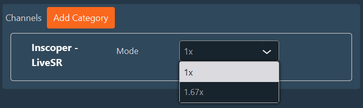
| Is the two-position intermediate magnification of a LiveSR module | LiveSR | 1 Generic TTL Output | 1x/1.67x drop-down list in the channel settings |
| Must receive one fixed-width TTL pulse per exposure (camera trigger) | Generic Trigger | 1 Generic TTL Output | None; selected as the camera trigger |
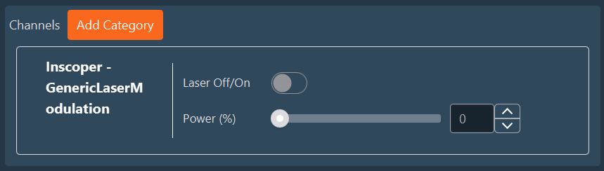
| Is a laser with an analog power input, with or without a digital on/off input | Generic Laser Modulation | 1 Generic Analog Output, plus 1 Generic TTL Output (optional) | Power slider and shutter in the channel settings |
Behavior common to TTL devices
Signal levels
1 drives the line high (5 V); 0 drives it low (0 V). There is no inversion setting: to invert a channel-dependent device, assign the opposite state to each channel; to invert a shutter, swap Open Value and Close Value in the Shutter Settings table (Expert Mode).
Stabilization delays
Fiber Switch, Mirror Switcher, and LiveSR each have two stabilization delays (µs, startup values). After each output change, the Device Controller waits for one of them before it executes the next command, to let the hardware settle:
- Stabilization Delay After 0 applies when the line goes low (0 V);
- Stabilization Delay After 1 applies when the line goes high (5 V).
Set a delay to 0 to skip the wait for that transition.
Laser Enable
Laser Enable drives one TTL line to a fixed level after the Device Controller initializes, and leaves it there. Use it for an enable, key switch, or interlock input that must be held high for the hardware to operate, and that the Imaging Software never needs to change.
| Parameter | Description | Default |
|---|---|---|
| Laser Enable | Level applied at startup: 1 enabled, 0 disabled. |
1 |
Laser Enable is the only parameter. It is a startup value, applied once the Device Controller has initialized. The device does not appear in the Imaging Software.
Laser Enable has no configurable stabilization delay. The Device Controller waits a fixed 1 ms after the line goes high, and does not wait after it goes low.
Do not use Laser Enable to switch a laser on and off between channels; use Generic Laser Modulation instead.
Fiber Switch
Fiber Switch drives one TTL line whose level is set per channel. Use it for any two-state element whose position depends on the channel being acquired, such as an optical fiber switch or a light-path selector.
| Parameter | Description | Default |
|---|---|---|
| Output | Line level: 0 low, 1 high. Set per channel in the Imaging Software. |
— |
| Stabilization Delay After 0 | Wait after the line goes low, in µs. See Stabilization delays. | 1000 µs |
| Stabilization Delay After 1 | Wait after the line goes high, in µs. | 1000 µs |
In the Imaging Software: an on/off switch in the channel settings.

Mirror Switcher
Mirror Switcher drives a motorized mirror that directs the light path either to a FRAP scanner or to widefield fluorescence illumination.
| Parameter | Description | Default |
|---|---|---|
| FRAP/Fluo Switcher | FRAP (line low) or Fluorescence (line high). Set per channel in the Imaging Software. |
— |
| Stabilization Delay After 0 | Wait after switching to FRAP, in µs. See Stabilization delays. |
1 000 000 µs (1 s) |
| Stabilization Delay After 1 | Wait after switching to Fluorescence, in µs. |
1 000 000 µs (1 s) |
In the Imaging Software: a FRAP/Fluorescence drop-down list in the channel settings.

The 1 s defaults cover the mechanical motion of a typical mirror. Reduce them only if the manufacturer specifies a shorter switching time. If the mirror is wired with the opposite polarity, swap the two labels in the value table of the control's advanced settings, in the Imaging Software layout.
LiveSR
LiveSR drives the two-position intermediate magnification changer of a LiveSR super-resolution module.
| Parameter | Description | Default |
|---|---|---|
| Mode | 1x (line low) or 1.67x (line high). Set per channel in the Imaging Software. |
— |
| Stabilization Delay After 0 | Wait after switching to 1x, in µs. See Stabilization delays. |
50 000 µs (50 ms) |
| Stabilization Delay After 1 | Wait after switching to 1.67x, in µs. |
50 000 µs (50 ms) |
In the Imaging Software: a 1x/1.67x drop-down list in the channel settings.
Note
Because the device declares a magnification, the Imaging Software includes the selected factor in the pixel size of the acquired images.
Generic Trigger
Generic Trigger emits one positive TTL pulse of fixed width each time it is fired. Use it to trigger a camera, or another instrument, that starts an exposure on a rising edge.
| Parameter | Description | Default |
|---|---|---|
| Trigger Width (us) | Duration of the high state of the pulse, in µs. The Device Controller waits for the full width before executing the next command. | 500 µs |
The line is driven low at initialization and at shutdown.
In the Imaging Software: no control. Generic Trigger is offered as a trigger source in the camera's device view when it is imported in the same device as the camera; see Camera trigger.
Generic Laser Modulation
Generic Laser Modulation drives a laser that accepts an analog power-control voltage and, optionally, a digital on/off (gate) input. The analog line sets the power; the on/off function is exposed as a shutter.
Shutter Control. The device panel offers two options:
| Option | Shutter driven by | When to choose it |
|---|---|---|
| TTL (default) | The Generic TTL Output, wired to the laser's digital input. The analog power is not changed when the shutter closes. | The laser has a digital modulation input. |
| No TTL | The Generic Analog Output itself: closing sets it to 0 V, opening restores the requested power. No TTL line is needed. | The laser has no digital input. |
| Parameter | Description | Default |
|---|---|---|
| Power (%) | Laser power, 0–100 %, step 0.01 %. The output voltage is Power × Maximum Voltage / 100. | 0 % |
| Laser Off/On or Laser Virtual Off/On | The shutter, according to Shutter Control. | Off (TTL), On (virtual) |
| Maximum Voltage (mV) | Voltage corresponding to 100 % power, 0–10 000 mV. Set it to the maximum input voltage the laser accepts. | 5000 mV |
| Power Delay | Wait after each power change, in µs. | 0 |
| Off Delay | Wait after the shutter closes, in µs. | 1000 µs |
| On Delay | Wait after the shutter opens, in µs. | 1000 µs |
Maximum Voltage and Power Delay are enabled under Advanced Parameters in the device panel by the Maximum Voltage and Power Stabilization Delay checkboxes; Off Delay and On Delay are both enabled by the Off/On Stabilization Delay checkbox. When a checkbox is cleared, the default above applies. The off and on delays apply with either Shutter Control option.
Warning
Check the analog input range in the laser manufacturer's specification before the first acquisition. The default Maximum Voltage of 5000 mV exceeds the input range of lasers rated for 0–1 V or 0–2.5 V.
In the Imaging Software: the power appears as an intensity slider in the channel settings. The shutter is listed in the Shutter Settings table, where its open and close values can be swapped in Expert Mode for a laser with an inverted digital input. Open only when imaging is cleared by default for this device.
See also: Connections, Shutter, Camera trigger, Configuring a device.