Connections
The connection view records how each function selected in the device view is wired to the Inscoper Device Controller. This mapping tells the Device Controller which physical port carries which command.
Opening the connection view
- Click Set Connection in the view of a device, or
- Advance through the setup wizard, which presents a Set Connection step for each imported device.
Only the connections that the current selection requires are shown. Clearing a function in the device view removes its connection cell from this view.
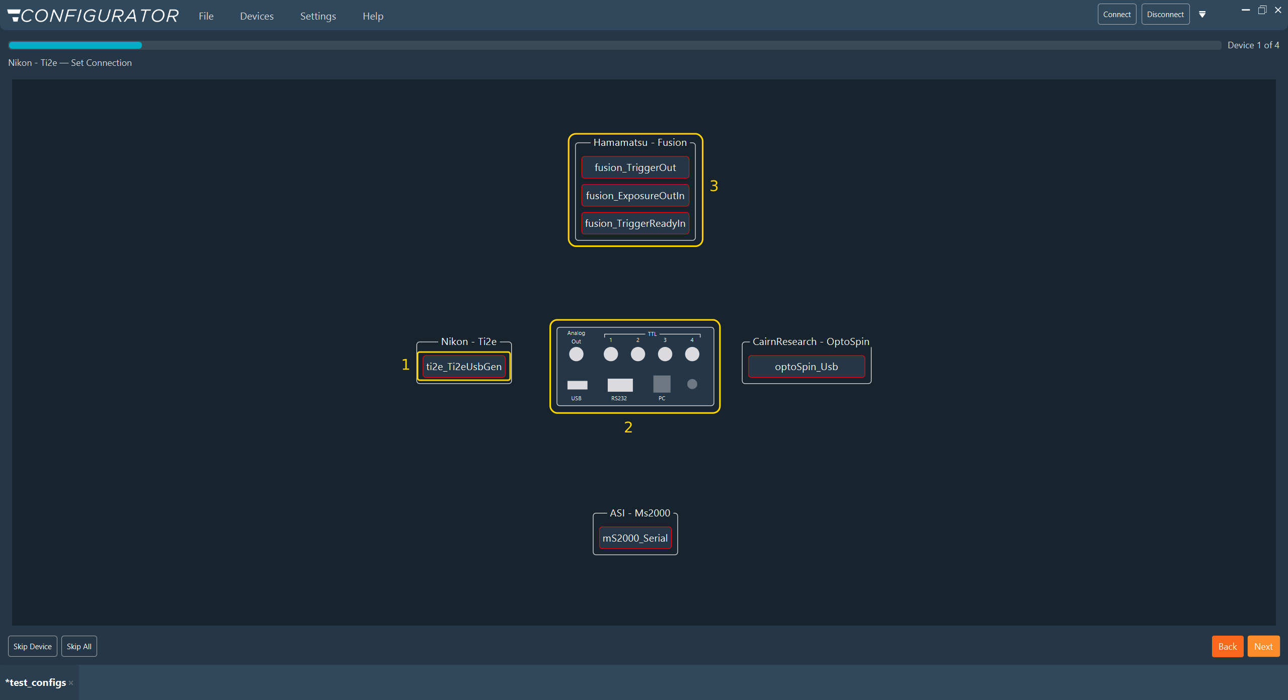
- Connection cell (1): One cell per function that requires wiring, grouped under the device it belongs to. Drag a cell onto a port to create the link.
- Device Controller panel (2): The ports of the connected Device Controller model. The panel shown here exposes an Analog Out line, four TTL lines, a USB port, an RS232 port, and the PC link.
- Unconnected cells (3): A red outline marks a cell whose link is still missing. Hover the cell to read why, for example
NOT_ENOUGH_OUTPUT, which reports how many outputs the function needs.
The port panel matches the Device Controller model that is connected. Models differ in the number of TTL, analog, and serial lines they expose.
Creating a link
- Locate the connection cell of the function to wire.
- Drag the cell onto the target port on the Device Controller panel.
- Repeat for every cell outlined in red.
When the link is accepted, the red outline is cleared and the connection icon of the device in the Imported Hardware tree turns from red to green.
Cable type
A cell can only be dropped on a port that carries the signal it needs. A serial function cannot be assigned to a TTL line, and a TTL trigger cannot be assigned to the RS232 port.
Tip
A single device can be dropped using different connectors. The available connectors for the selected device will be highlighted in green on the Device Controller panel. For example, the Lumencor SpectraX can be controlled via a USB or RS232 port.
Assigning a USB device
Dropping a cell on the USB port opens the USB configuration window for that device.
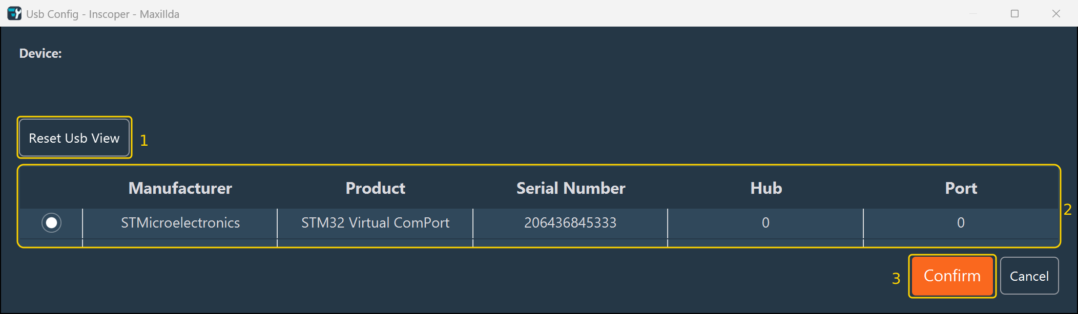
The table lists the USB devices the Device Controller currently sees, with their Manufacturer, Product, Serial number, Hub, and Port. Enabling Expert Mode adds four columns: VID, PID, Num Interface (number of USB interfaces the device exposes), and Driver.
- If the device is missing from the table, click Reset Usb View (1). The Device Controller rescans its USB bus, then the table is reloaded.
- Select the row of the device in the table (2).
- Click Confirm (3) to apply the selected row to the device, or Cancel to close the window without changing the assignment.
Note
An empty table means that the Device Controller does not currently see any USB device. Verify that the instrument is powered and cabled, then click Reset Usb View. Allow the delay set by Seconds To Wait After USB Reset in the application settings before the table is repopulated.
Internal hub
On Device Controller models other than type S, the first row of the USB list corresponds to the internal hub of the controller. It is present for diagnostic purposes and confirms that internal communication is functional.
Arranging the view
| Action | Control |
|---|---|
| Move a device group or the Device Controller panel | Drag it. |
| Pan the workspace | Drag the background. |
| Zoom | Scroll wheel. |
| Reset the view | Double-click the scroll wheel. |
| Manage the arrow | Right click to change arrow's color or delete arrow. |
Rearranging the view is cosmetic. It has no effect on the configuration.
Checking the result
A configuration is complete with respect to connections when every entry in the Imported Hardware tree carries a green connection icon. The Configurator also reports every missing connection when you click Next; see Validation.
Next step: Proceed to Imaging Software layout.